This HTML edition contains selectable text extracted from the original PDF. Layout-aware OCR was used to recover reading order, figures and equations; minor recognition errors may remain. Consult the PDF for the authoritative layout, figures and equations.
4 1st Tech Cof Sing Transport
March 28-30, 1979 Les Vegas
PIPELINING OF COARSE COAL AS A STABILIZED SLURRY—ANOTHER VIEWPOINT
Dr. A.D. Thomas
M.D. Research Company Pty Ltd.
North Ryde, N.S.W., Australia
1. INTRODUCTION
Increasing interest has recently been shown in the possibility of transporting coarse coal as a "stabilized" slurry. (e.g. Pertuit et al, 1978). Such a slurry would be formed by grinding a small proportion of the coal very fine to form a viscous "vehicle" or "carrier" and this would support the coarse particles enabling transport under laminar flow. Furthermore such slurries would be stable under shutdown conditions, the vehicle being sufficiently "viscous" to prevent the coarse particles settling.
Pertuit et al (1978) discussed the advantages of this advantages over conventional fine particle long distance slurries (e.g. Black Mesa) are the greater product acceptance of coarse coal and lower size reduction and dewatering costs. These advantages are obtained at the expense of higher pressure gradients but in spite of this the overall transport costs look promising compared to conventional slurry systems.
In this paper the stabilized slurry concept is investigated firstly by pipeloop testing, under laminar flow conditions, simulated slurries consisting of coarse particles in highly viscous Newtonian fluids. These results are compared with a theory based on a sliding bed concept. Next, actual stabilized slurries are tested in the same pipeloops and a modification to the above theory is proposed to explain their behaviour.
2. STABILITY UNDER STATIC CONDITIONS
For obvious reasons the ability to restart a pipeline full of slurry on shutdown becomes of paramount importance once the pipeline length exceeds a few kilometres. Thus the static stability of the proposed stabilized slurries is a major advantage. However, it must be realized that existing long distance slurries already have this ability to be restarted (Wasp, 1969). In both cases it is achieved in the same way—by having a fine particle flocculated vehicle sufficiently "viscous" to trap the coarser particles and prevent them settling preferentially. The physical mechanisms whereby this occurs have received little attention in the literature but it is clear from the limited works available (e.g. Ansley & Smith, 1967; A.D. Thomas, 1977; Traynis, 1977) that static stability occurs when the yield stress of the slurry is sufficient to support the coarsest particles. The yield stress arises from the strength of the floc structure which forms under static conditions with flocculated suspensions (D.G. Thomas, 1961). Two
requirements are necessary for this to occur. Firstly some particles must be smaller than about 10 microns and secondly these particles must be flocculated. Because of the first requirement it is essential for static stability that there be some fines present. The second requirement is usually not a practical problem as flocculation tends to be the rule rather than the exception in industrial processes.
Provided the yield stress is sufficiently large to support the largest particles such particles will remain suspended under static conditions indefinitely. (e.g. Halvorsen, 1976). In a previous paper (A.D. Thomas, 1977) the author derived a simple criterion to determine the yield stress required to ensure stability of a certain size particle namely
where is the yield stress of the vehicle, is the maximum particle size, is the gravitational acceleration, and and are the particle and vehicle densities respectively. Unknown to the author, Russian workers had previously arrived at an equation of identical form with the constant given as between .083 to 0.10 (Traynis, 1977) so that equation 1 is now fairly well established.
3. LAMINAR FLOW AND STATIC STABILITY
If a slurry is made up totally of particles less than about 10 microns in size, (i.e. all particles affected by flocculation), laminar flow in both vertical and horizontal pipes is readily attainable. Such would be the case for the vehicle portion of a stabilized slurry. However, once coarser particles are added laminar flow in a horizontal pipe may not be possible due to settling effects. Obviously in any particular situation a certain minimum vehicle consistency is required before laminar flow is possible. Traynis (1977) states that if the slurry is statically stable then laminar flow is possible and this was also inferred by Pertuit et al (1978). However, it has been shown by the author, (A.D. Thomas, 1978), that in some cases this is not true. Further evidence of this is suggested by the fact that most existing "long distance" slurries, whilst statically stable, are known to deposit out under turbulent conditions without laminar flow being possible. Thus although the satisfying of equation 1 should ensure static stability it does not necessarily follow that laminar flow is possible. It is now evident that although both the existing long distance slurries and the proposed stabilized slurries are statically stable the latter have the additional property of being able to flow under laminar conditions. This will generally re-
In-situ Concentration
(volume %)
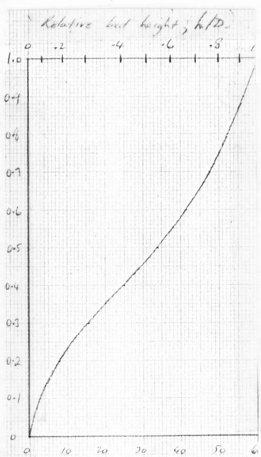
Relative bed height, h/D
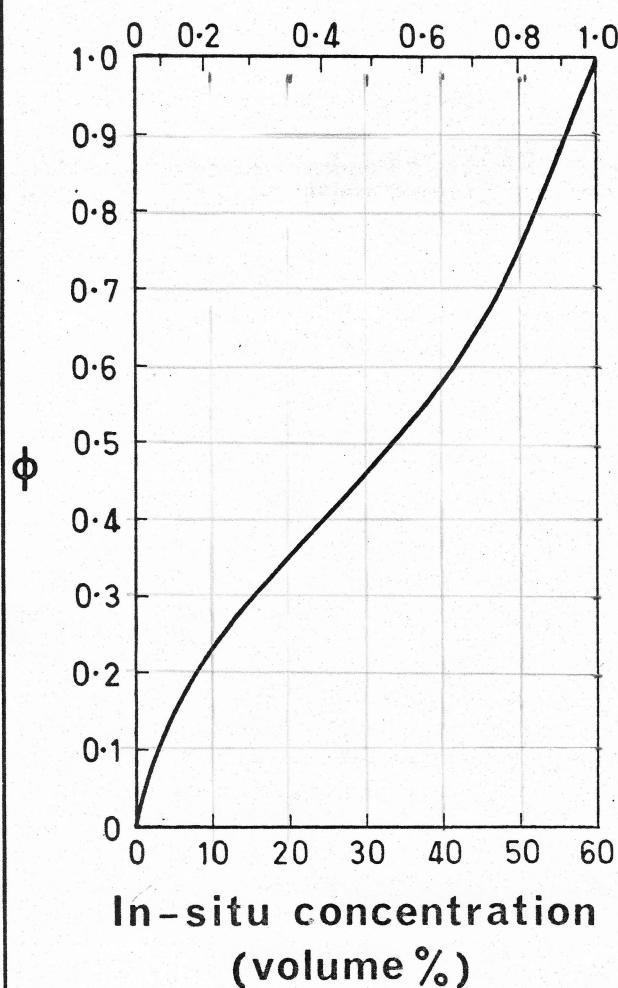
FIGURE 1
VARIATION OF FUNCTION WITH CONCENTRATION AND h/D.
quire a more viscous vehicle than that required to obtain static stability alone.
4. LAMINAR FLOW OF NEWTONIAN SLURRIES
4.1 Physical Analysis of Laminar Slurry Flow with Newtonian Vehicle
Consider a suspension of coarse particles in a viscous Newtonian fluid. In a vertical pipe homogeneous laminar flow would be obtainable. Similarly in a horizontal pipe the same would apply provided the length of the pipe was not long enough to allow significant settling. However, given sufficient pipe length, it would be expected that the particles would gravitate to the bottom since, unlike the turbulent flow situation, the particles reach the bottom they will be transported as a sliding or saltating layer of particles with solid/solid frictional
contact occurring between this sliding layer and the pipe wall. At this stage the situation is analogous to the turbulent flow transport of very coarse particles where all of the particles are being transported as a sliding or saltating bed with no turbulent particle support. This turbulent flow case has recently, and his theory should apply equally as well to the laminar flow case.
Wilson's theory is based on a simple force balance between the resisting force acting on the bed due to the solid friction and the driving force due to the fluid pressure gradient. Incipient deposition occurs when these two forces exactly balance each other. His turbulent flow theory allows for the effect of the different surface roughness of the top of the sliding bed and the pipe wall. For laminar flow, fluid resistance is independent of surface roughness and for this situation it can be shown that Wilson's theory indicates incipient deposition occurs when the slurry pressure gradient equals given by
where is the co-efficient of sliding friction between the bed and the pipe wall (Wilson takes as 0.4).
is the maximum packing concentration by volume (= 0.6 for narrow size distributions)
is the fluid density
is relative solids density
and is a geometrical function which depends on the height of the sliding bed (i.e. the in-situ concentration of solids in the bed). If is taken as 0.6 it can be shown, using Wilson's equations, that is as given by Figure 1 either in terms of the in-situ concentration of sliding solids or the ratio of bed height to pipe diameter (h/D).
The most important consequence of equation 2 is that deposition occurs at a constant value of slurry pressure gradient regardless of pipe size . This means that the pressure gradient becomes increasingly uneconomic as the pipe size increases. For example equation 2 indicates pressure gradients of the order of (0.1 ft water/ft) for coal at 40% concentration, which although not unreasonable in small size pipes, is a considerable disadvantage in larger pipes (c.f. the pressure gradient for the 450 mm (18 inch) Black Mesa pipeline which, from the information supplied by Love (1969) is around (0.1 ft water/ft).
4.2 Pipe Length Required for Particles to Settle with Newtonian Vehicle
Consider a pipeloop through which a Newtonian slurry is being pumped under laminar flow. At the entrance to the line, immediately following the pump, the particles can be assumed homogeneously distributed. As the slurry travels along the pipeline the particles slowly settle so that, as a first approximation, after a distance the particles have settled a height given by
where is the free settling velocity of the particles and is the mean flow velocity. (Throughout this paper will be calculated as for spheres). All particles will have fully settled when , i.e. after a pipe length, , given by
Of course the actual situation is far more complicated than this due to the influence of the velocity profile, the pipe shape and hindered settling effects at higher concentration but a more detailed analysis is not warranted at this stage.
4.3 Pressure Drop in "Entrance" Region
Consider a pipeloop through which a slurry is flowing under laminar conditions. At distances from the entrance less than the particles are still settling and so a non-equilibrium situation exists. is in effect the entry length. Thus, just as single phase laminar or turbulent flow requires an entry length before fully developed flow is reached, so the laminar flow of a slurry requires a certain entry length before the equilibrium sliding bed flow is attained. In some cases this latter entry length can theoretically be many kilometres in length. As a consequence data obtained in a test loop may not pertain to fully developed flow.
In this entry region the pressure gradient can be estimated by the following procedure. At any axial position the vertical height the particles have fallen is given by equation 3. The proportion of solids in the sliding bed can therefore be calculated.
Once this is known can be obtained from Figure 1 and the pressure gradient obtained from equation 2. It should be noted that equation 2 strictly only applies at incipient deposition but it can be used to give a rough estimate of the pressure gradient in other cases.
4.4 Comparison With Pipe Loop Results—Newtonian Fluids
Equations 2 to 4 provide means of estimating the behaviour of Newtonian based slurries. This predicted behaviour will now be compared with experimental results for some sugar/water solutions in viscous Newtonian fluids, the latter being sugar/water solutions at various concentrations.
4.4.1 Description of Pipe Loops
105 mm (4 inch)
The initial experiments were conducted with the 105 mm (4 inch) pipe loop in the configuration shown in Figure 2(a). At this stage pipe length was not known to be of importance and although there were two viewing sections most of the observations were made at A. The slurry would be expected to be remixed in the two right angled beds upstream of A so that the length to A is taken as 6m. Flowrate was measured by a venturi and occasionally checked by timing a sample, whilst concentration was determined by sampling.
18.9 mm (3/4 inch) and 9.41 mm (3/8 inch)
These two loops were schematically similar to the above loop. They has a 4.3 m (14 ft) long outward leg with the middle of the 2.3 m (7.5 ft) long pressure measuring section 2.9 m (9.5 ft) from the pump and the viewing section 4 m (13 ft) from the pump. Flowrates were measured by diverting the flow and timing a sample.
4.4.2 Experimental Results for Various Size Sands
Figure 3 shows the results for 12% concentration of 0.18 mm sand (narrow size distribution with 90% of particles between 0.12 and 0.30 mm) at two fluid viscosities of 60 cP and 95 cP in the 105 mm loop. It can be seen that laminar flow was only obtainable at the higher viscosity. In this case the slurry pressure gradient almost parallels the fluid only laminar pressure gradient suggesting near homogeneous flow with little stratification. At 0.89 ms -1 a 3 mm high stationary bed was observed.
Figure 4 shows results for the same pipeloop with 12% concentration of 0.82 mm sand (90% between 0.60 mm and 1.05 mm) in sugar solutions of three different viscosities, 115, 155 and 270 cP. At the lowest viscosity laminar flow was not obtainable before deposition occurred as was evidenced by the laminar/turbulent transition bursts clearly visible at deposition.
The fine, 0.18 mm, sand was next tested at the same concentration of 12% in the 18.9 mm (3/4 inch) pipe loop in a fluid of viscosity 22 cP. The results are shown in Figure 5. Also shown are the results for a slightly finer (0.13 mm) sand at the same concentration in the 9.41 mm (3/8 inch) pipeloop in a fluid of viscosity of 5.3 cP.
4.4.3 Comparison With Theory
How do these results compare with the previously outlined theory? Consider first the 0.18 mm sand in the 105 mm pipe loop. Although this sand could be termed of narrow size distribution, because of the strong dependence of on in equation 4 it is thought most appropriate to use the particle size pertaining to 5 cumulative per cent greater than (i.e. 0.30 mm) rather than the median particle size. For such size particles settling in the 95 cP fluid ( ) . At the observed deposit velocity of 0.9 ms -1 equation 4 indicates an entry length of 135 m meaning that everywhere within the pipe loop the flow is still developing. Equation 3 indicates that at station A and 10 mm in the middle of the pressure measuring section so that the area fraction originally occupied by the now settled particles was 0.0165 and 0.049 respectively. But these particles settle down to occupy only of their original area so that and .033, i.e. and 3.5 mm respectively. Using Figure 1 and equation 2 this latter value indicates a pressure gradient at deposition of 280 .
Similar calculations have been performed for the other experiments and the results are tabulated in Table 1 together with the measured values. It can be seen that broad agreement is obtained. The first slurry is far from fully developed and so a low pressure drop and bed
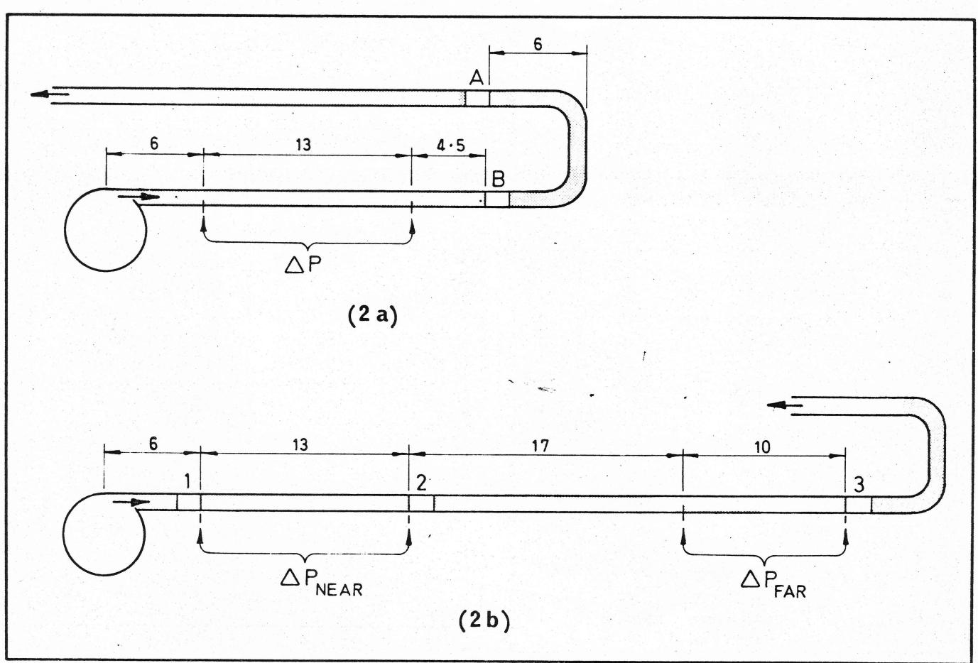
FIGURE 2
DESCRIPTION OF ORIGINAL (a) AND EXTENDED (b) 105 MM (4 INCH) PIPELOOPS. ALL DIMENSIONS IN METRES.
height is both predicted and observed. This also explains the near homogeneous flow noted previously. The successive slurries are progressively more developed resulting in increasingly larger pressure drops and bed heights. The observed bed heights are consistently higher than the predictions but this is to be expected since the latter refer to the height at incipient deposition whereas the observed values are necessarily obtained at a lower velocity.
Note that, whereas laminar flow was possible with the 0.18 mm sand in a 22 cP fluid in the 18.9 mm pipe, a viscosity of 60 cP was insufficient to obtain laminar flow with the same sand in the 105 mm loop (Figure 3). Furthermore a marginally finer sand in the 9.41 mm loop required a viscosity of only 5.3 cP.
4.4.4 Testing of 0.31 mm Sand in Extended 105 mm Pipe Loop
Although the experiments just discussed supported the proposed laminar flow theory, to prove it more conclusively it was desirable that simultaneous observations and pressure measurements be made at different axial positions along the pipe loop. For this purpose the 105 mm pipe loop was extended to roughly twice the length with additional pressure tappings and viewing sections incorporated. The dimensions are given in Figure 2(b).
Figures 6(a) to (d) show the results obtained at various concentrations and viscosities. The sand of medium particle size 0.31 mm had a size distribution such that 90% of the particles lay between 0.19 and 0.49 mm. In every case the measured pressure gradient was highest at the downstream pressure tappings. Further evidence of the "length effect" is provided by the observations of sliding and stationary bed heights at the three viewing sections 1, 2 & 3. These heights are given in Figures 6(a) to 6(d). All of these results can be shown to be consistent with the previously presented theory.
It should be noted that tests with the same sand in water (i.e. turbulent flow) revealed no differences in either the pressure gradients along the pipe length or the bed heights at viewing stations 1, 2 & 3. This therefore confirms that the length effects observed are a phenomenon peculiar to laminar flow.
4.5 Summarized Conclusions for Newtonian Vehicle
It has been fairly conclusively shown that the laminar flow of coarse particles in a viscous Newtonian fluid can be analysed by assuming that the particles slowly settle as they travel along the pipeline. When they reach the bottom they form a sliding bed the height of which deter-
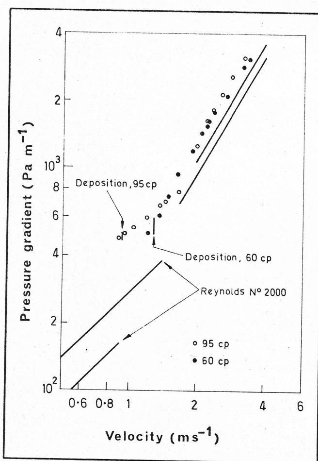
FIGURE 3
RESULTS FOR 0.18 MM SAND IN NEWTONIAN FLUIDS OF VISCOSITIES 60 AND 95 CP. TESTED IN 105 MM PIPELOOP. CONCENTRATION 12% BY VOLUME. FULL LINES REPRESENT LAMINAR AND TURBULENT BEHAVIOUR FOR FLUID ALONE.
mines the pressure gradient and the deposition criteria. The major consequences of this theory are:
- a) The obtaining of laminar flow without deposition in tests in a small diameter pipe loop does not necessarily mean that the same slurry can flow in a laminar manner without deposition (stationary bed) in a larger size pipe.
- b) The obtaining of laminar flow without deposition in tests in a short pipe loop does not necessarily mean that laminar flow without deposition can be obtained with the same slurry in the same diameter pipe of longer length.
- c) Given sufficient pipe length for full settling to occur the pressure gradient required to prevent deposition under laminar conditions is approximately constant for a particular commodity for all pipe sizes. This pressure gradient will be similar to that needed if the same coarse particles were transported in water under turbulent conditions (since equation 2 describes both situations) indicating little advantage in using a high viscosity Newtonian vehicle.
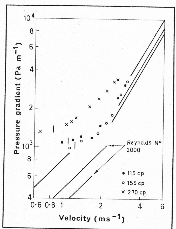
FIGURE 4
RESULTS FOR 0.82 MM SAND IN NEWTONIAN FLUIDS OF VISCOSITIES 115, 155 AND 270 CP. IN 105 MM PIPELOOP. CONCENTRATION 12% BY VOLUME. FULL LINES REPRESENT LAMINAR AND TURBULENT BEHAVIOUR FOR FLUID ALONE.
5. LAMINAR FLOW OF STABILIZED SLURRIES (NON-NEWTONIAN)
5.1 Tests in Extended 105 mm (4 inch) Pipe Loop
The length effect having been reasonably confirmed with Newtonian fluids the next step was to test a stabilized slurry in the extended 105 mm (4 inch) pipe loop. The slurry chosen was a mixture of nominal mm + 1 mm coal (median size 2.3 mm with 90% between 0.6 mm and 5.8 mm) in a China clay vehicle. The rheological properties of the clay had previously been determined in a tube viscometer and various pipe loops (A.D. Thomas, 1978) and it was found to follow typical Bingham plastic behaviour having a yield stress of 3 Pa and a plastic viscosity of 4 cP. The solids density of the coal was kg , giving it a relative density in the vehicle of 1.22.
Application of equation 1 indicates that this slurry should be statically stable. This was confirmed by the absence of preferential settling after having previously stood, for 15 months in drums. Even after this time the coarsest particles were still suspended throughout the slurry.
Tests were performed at two concentrations of coal in the clay suspension, namely 23% and 48% by volume.
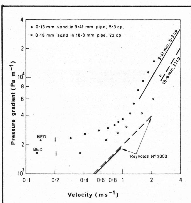
FIGURE 5
RESULTS FOR FINE SANDS IN SMALL PIPE LOOPS WITH NEWTONIAN FLUIDS. CONCENTRATION 12% BY VOLUME. FULL AND DASHED LINES REPRESENT LAMINAR AND TURBULENT BEHAVIOUR FOR FLUID ALONE.
The results are presented in Figure 7. In both cases stationary beds were evident at all three visual sections at velocities below . Some observations from these tests were:
- a) Once again the measured pressure gradient was higher at the downstream tappings. However an interesting feature was that this difference in pressure gradient between the upstream and downstream tappings was more evident in the laminar/turbulent transition region ( ). Once pure laminar flow was obtained the difference became much less. This effect has also been noticed in other tests not presented here.
- b) The exact heights of sliding beds were not easy to determine. This was particularly so at low velocities where the slurries tended to move en bloc even though a vertical concentration gradient was clearly evident. Furthermore the beds did not appear to be so compact as with Newtonian fluids.
- c) In spite of the difficulty in observing the actual bed heights there did not appear to be any significant differences in bed height between the three viewing stations.
5.2 Analysis of Results
If it is tentatively assumed that all of the coal has settled to form a sliding bed then application of equation 2 indicates pressure gradients at deposition of 400 and 750
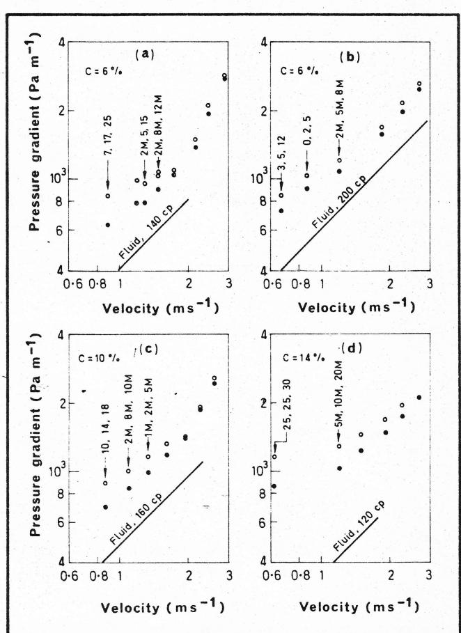
FIGURE 6
RESULTS FOR 0.31 MM SAND IN EXTENDED 105 MM PIPELOOP AT VARIOUS CONCENTRATIONS AND FLUID VISCOSITIES. OPEN DATA POINTS DENOTE MEASURED PRESSURE GRADIENTS AT FAR TAPPINGS (SEE FIGURE 2(b)); CLOSED DATA POINTS DENOTE NEAR TAPPINGS. THE GROUPS OF THREE NUMBERS WITH ARROWS INDICATE THE OBSERVED BED HEIGHTS IN MM AT STATIONS 1, 2 & 3 RESPECTIVELY. M INDICATES A MOVING BED.
for the 23 and 48% concentration respectively. The observed values are about one half of these predictions. This could indicate that complete settling has not occurred in the pipe length available, but, the use of equation 3 and 4 to check whether this is the case is made impossible because of the uncertainty regarding the settling rates of coarse particles in a flowing Bingham plastic.
The settling of solid spheres in stationary Bingham plastics is far from satisfactorily understood at present (e.g., Ansley & Smith, 1967) so that an analysis of the settling of particles in a horizontally sheared Bingham plastic is a very difficult problem. The settling velocity, , would no longer be constant due to the different resistance of the sheared layer near the walls compared with the less sheared core region. At high shear rates (high flow velocities and small pipe sizes) shearing will occur over the whole pipe area and the floc structure will be considerably broken down resulting in relatively high par-
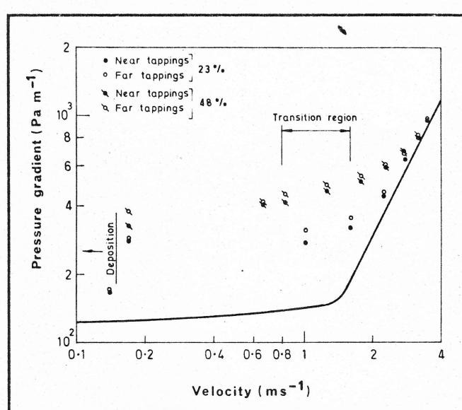
FIGURE 7
RESULTS FOR 8x1 MM COAL IN CLAY SUSPENSION IN EXTENDED 105 MM PIPELOOP. FULL LINES REPRESENT BEHAVIOUR OF CLAY SUSPENSION ALONE.
ticle settling rates. In contrast, at low shear rates (low flow velocities and large pipe sizes), most shearing will occur near the walls with the floc structure in the core region remaining largely intact. In true Bingham plastic flow the core region could be completely unsheared so that the floc structure would be completely unbroken and so theoretically be able to support some particles indefinitely just as under static conditions. To what extent this occurs in practice is at present unknown. The author's experience has been that with coarse particles present in flowing Bingham plastics there is generally observed a vertical velocity and concentration profile indicating that no completely unsheared region exists. This would suggest that, given sufficient pipe length, the coarse particles would always eventually settle.
Because of the uncertainty as to the degree of settling which has occurred in the pipe loop length these stabilized slurry tests are not easy to interpret. The observed
behaviour could be explained by the previous theory but there are a number of factors which suggest that a different explanation exists. This matter will be discussed shortly in Section 5.4.
5.3 The Work of Elliot & Glidden (1970)
Elliot & Glidden (1970) were among the first to investigate the concept of laminar flow transport of coarse particles. They tested various coal slurries in pipeloops up to 1.6 km (1 mile) in length and 250 mm (10 inch) in diameter. Their results would seem to disprove the theory advanced here as slurries were successfully pumped over long distances apparently without settling occurring in the 100 mm (4 inch) pipe loop, although, it should be noted that the pressure gradient in that pipe loop was almost what would be expected from a sliding bed approach.
Of greater significance are their tests in the larger (250 mm) pipe loop. In this loop they obtained laminar flow without deposition at pressure gradients as low as 110 Pa m -1 . The only way that such low pressure gradients could be explained by the previous sliding bed theory is if incomplete settling had occurred in the relatively short length loop. (It was 365 m (1200 ft) long resulting in a similar L/D ratio as the author's 105 mm (4 inch) loop). However an alternative, and it is believed, more plausible explanation, is provided by the theory advanced in the following section.
5.4 Proposed Theory for Stabilized Slurries
Although the results for Newtonian based slurries are satisfactorily explained by the previous theory the results obtained with stabilized slurries both here and by Elliot & Glidden (1970) suggest some additional phenomenon. It is now proposed that with stabilized slurries, although settling does occur as the slurry flows along the pipeline, the settled bed is less compacted than with Newtonian vehicles. This results in less particle/particle interaction and hence lower pressure gradients. The lower degree of compaction could be due to the coarse particles being kept separated by the compressible flocs. This would be more likely to occur at low shear rates when the flocs are not broken down to any great extent and would explain the en bloc movement observed at low velocities in Sec-
TABLE 1
COMPARISON BETWEEN THEORY AND EXPERIMENT FOR SANDS IN NEWTONIAN FLUIDS
ALL AT A CONCENTRATION OF 12% BY VOLUME
| Particle Size (mm) | Fluid Viscosity (cp) | Pipe (mm) | Pressure Drop (Pa m -1 ) | Bed Height (mm) | Comments | ||
|---|---|---|---|---|---|---|---|
| Predicted | Measured | Predicted | Measured | ||||
| 0.18 | 95 | 105 | 280 | 500 | 1.7 | 3 | Still developing (L s = 135 m) |
| 0.82 | 155 | 105 | 1020 | 1060 | 8 | 25 | Partly developed (L s = 26 m) |
| 0.82 | 270 | 105 | 900 | 1400 | 7 | 30 | Partly developed (L s = 26 m) |
| 0.18 | 22 | 18.9 | 1700 | 1600 | 5 | 6 | Fully developed (L s = 1.8 m) |
| 0.13 | 5.3 | 9.41 | 1800 | 2200 | 2.5 | 3 | Fully developed (L s = 2.2 m) |
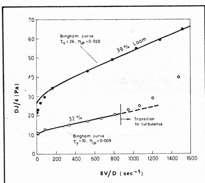
FIGURE 8
RESULTS FOR TWO CONCENTRATIONS OF LOAM IN 18.9 MM PIPELOOP. FULL LINES REPRESENT FITTED BINGHAM CURVES.
tion 5.1. In the laminar/turbulent transition regime the flocs are disrupted by the turbulent bursts so that the situation would be closer to the Newtonian case. This could explain the greater differences between the upstream and downstream pressure gradient observed in the transition regime, (see Section 5.1).
The degree of compaction of the bed will depend on the floc strength. Under static conditions the yield stress is a measure of the strength of the flocs but in a flowing pipe they strength will be reduced by the shearing action and will probably be function of the shear rate . ( is velocity, is pipe diameter). For a given velocity the shear rate is less in a larger pipe meaning that the floc strength will be higher and the settled bed less compact than in a smaller pipe. The result is that instead of the pressure gradient at deposition being constant for all pipe sizes, as the sliding bed theory predicts for Newtonian vehicles, it will decrease with larger pipe sizes . The size of the decrease will depend on the relative strength of the floc structure and the size of the particles.
In some cases the effect may be sufficiently great to cause to vary inversely with pipe diameter meaning that deposition occurs at a constant value of wall shear stress, , in agreement with the previous findings of the author (A.D. Thomas, 1978). This would also mean that the usual scale up methods for pressure gradient would apply so that the statement by Pertuit et al (1978) that: "the stab-flo headlosses decrease in proportion to the increase in pipe diameter" would be correct. However this is not true in general. The behaviour of a particular stabilized slurry could range anywhere from this ideal case to the worst case approaching the Newtonian vehicle situation where is constant for all pipe sizes. Unfortunately no means are presently available to quantify this effect.
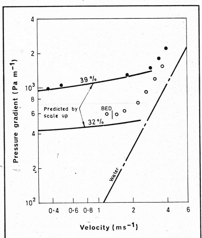
FIGURE 9
RESULTS FOR TWO CONCENTRATIONS OF LOAM IN 105 MM PIPELOOP. FULL LINES REPRESENT BEHAVIOUR PREDICTED BY SCALING UP FROM THE 18.9 MM PIPELOOP RESULTS.
5.5 Consequences for Stabilized Slurry Concept
The major consequence as regards the pumping of stabilized slurries is that the design of such systems is complicated both by test loop length effects and by the uncertainty as to the exact influence of floc support. The problem is best illustrated by an example. Figure 8 shows the results of tests by the author in the 18.9 mm (3/4 inch) pipeloop of loam (a mixture of coarse (0.35 mm) sand and clay) at two concentrations, 32 and 39% by volume. (These tests have previously been referred to, A.D. Thomas (1978), but no details were presented at that time). The results are plotted as wall shear stress versus apparent shear rate. In both cases velocities as low as ( ) were obtained with no deposition observed. Both slurries were statically stable. The full lines drawn through the data represent the theoretical plastic viscosities indicated. The laminar flow data are seen to fit these curves reasonably well especially for the 32% concentration.
Having obtained such data one would be tempted to assume that the behaviour in a larger size pipe could be calculated by direct scale-up from this plot following the method of Bowen, (1961). Figure 9 shows the resulting laminar flow predictions for a 105 mm (4 inch) pipe, along with experimental data obtained at the two concentrations in the pipe loop described in Figure 2(a). The
behaviour of the 39% concentration slurry is predicted quite closely and no stationary deposit was observed even at the lowest velocity tested. Thus the scale-up technique can be considered successful. However, the 32% concentration case was not so successful. Laminar flow was barely possible before a stationary 10 mm (0.4 inch) high bed appeared at . Thus, supposing for example that the design was based on an operating velocity in the 105 mm (4 inch) pipe of , it can be seen that this would not be obtainable and blockage would probably result.
This example has served to show that, just as in the Newtonian vehicle case, successful laminar flow operation in a particular test loop does not necessarily mean that the same slurry can flow laminarly in a larger size pipe. Presumably, even though laminar flow was successfully obtained in the 105 mm (4 inch) pipeloop at 39% concentration, if that slurry were pumped in a larger size pipe laminar flow without deposition might not be possible.
6. CONCLUSIONS
The results of tests with coarse particles transported under laminar flow conditions in viscous Newtonian fluids can be explained by assuming that the particles slowly settle as they travel along the pipeline. When they reach the bottom they form a sliding bed the height of which determines the pressure gradient required to prevent deposition. The major consequences were summarized in Section 4.5, the net result being that such slurries would not be attractive propositions due to the high pressure gradients required especially in large pipes.
Available results obtained with stabilized slurries, i.e., coarse particles suspended in flocculated non-Newtonian vehicles, are less conclusive and further work is required. Nevertheless in this paper a qualitative theory has been advanced for such slurries which could explain their behaviour. As in the Newtonian case this theory assumes that slow settling takes place through a sliding bed. However, in this case the sliding bed is less compacted, the particles being kept apart by the compressible floc structure. This results in less particle/particle interaction and lower pressure gradients. Although this improves the situation and makes the stabilized slurry concept commercially feasible the design of such systems needs to be handled with care. Scale up on pipe diameter is difficult and ideally tests would need to be carried out on the full size pipe. Even then "length" effects can obscure the issue unless a pipeloop of sufficient length is employed.
The major conclusions as regards the stabilized slurry concept are summarized below:
- a) That a particular slurry is stable under static conditions certainly does not necessarily mean laminar flow is possible in all pipe sizes.
- b) Even if pipe loop tests reveal that laminar flow is possible in a particular size pipe it does not necessarily follow that laminar flow is possible in a larger pipe with the same slurry.
- c) Even if laminar flow is possible in a larger pipe the pressure gradient may be considerably higher than indicated from normal scale up relations. Depending on the particular slurry properties, the variation of pressure gradient with pipe size can lie anywhere between the ideal situation, where J varies inversely with pipe diameter, to the worst situation, given by the Newtonian vehicle theory, where J is constant for all pipe sizes.
7. ACKNOWLEDGEMENTS
The author wishes to thank M.D. Research Co. Pty Ltd. for acknowledgements to publish this paper. In addition who first suggested to the author the possibility of slow settling of particles along the pipe length in laminar flow.
Editors Note: Dr. Thomas was unable to deliver the paper personally. Norman T. Cowper, an independent slurry consultant from Sydney delivered the paper in his stead. Mr. Cowper also answered questions from the floor.
8. REFERENCES
- 1. Ansley, R. W. and Smith, T. N. (1967). Motion of spherical particles in a Bingham plastic, A. I. Ch. E. Jnl , Vol. 13, No. 6, pp. 1193-1196.
- 2. Bowen, R. L. (1961). Designing laminar flow systems, Chemical Engineering , June 12, pp. 243-248.
- 3. Elliot, D. E. and Gliddon, B. J. (1970). Hydraulic Transport of coal at high concentration, Proceedings 1st Int. Conference on the Hydraulic Transport of Solids in Pipes , Organised by Brit. Hydromech. Res. Assoc., Cranfield, paper G2.
- 4. Halvorsen, W. J. (1976). Slurry pipeline hydraulics improved, The Oil and Gas Jnl , March 22, pp. 62-66.
- 5. Love, F. H. (1969). The Black Mesa story, Pipeline Engineer , Nov. pp. 38-42.
- 6. Pertuit, P., Tennant, J. D., Lawler, H. L. and Cowper, N. T. (1978). Application of stabilised slurry concepts of pipeline transportation of large particle coal., Proc. 3rd Int. Tech. Conf. on Slurry Transportation , March 29-31, Las Vegas, pp. 164-176.
- 7. Thomas, A. D. (1978). Coarse particles in a heavy medium—turbulent pressure drop reduction and deposition under laminar flow. Proc. 5th Int. Conf. on the Hydraulic Transport of Solids in Pipes , May 8-11, Hannover, Paper D5.
- 8. Thomas, A. D. (1977). A rational design philosophy for long distance slurry pipelines, Chemical Engineering in Australia, the Trans. of the Instn. of Engineers , Aust. pp. 22-33.
- 9. Thomas, D. G. (1961). Laminar flow properties of flocculated suspensions, A. I. Ch. E. Jnl , Vol. 7, No. 3, Sept., pp. 431-437.
- 10. Traynis, V. V. (1977). Parameters and flow regimes for hydraulic transport of coal by pipeline, Translated from Russian by Terraspace Inc., Rockville, Md., U.S.A.
- 11. Wasp, E. J. (1969). What slurry pipelining is all about, Pipeline Engineer , Nov. pp. 30-35.
- 12. Wilson, K. C. (1974). Co-ordinates for the limit of deposition in pipeline flow, Proc. 3rd Int. Conf. on the Hydraulic Transport of Solids in Pipes, May 15th-17th, Golden, Colorado, U.S.A. Paper E1.
QUESTIONS AND ANSWERS
DR. STRIPLING: My name is Travis Stripling with Brown and Root. I have a question. Are you familiar with the work by Eliot and Glidden? It was published at Hydro-Transport. One concerning pressure loss calculations for coal slurry, stabilized coal slurry. They did experimental studies on pipes from about one and a half to ten inches in diameter.
MR. COWPER: Yes. I am very familiar with that.
DR. STRIPLING: My question is: they put forth the concept you can scale to larger pipe sizes using a generalized Reynolds number type correlation. How do your results affect this concept? Is that still valid according to your results?
MR. COWPER: If it's a truly stabilized slurry they're valid. Really only scaling up on a straight shear stress ver-
sus sheer rate basis, so there's validity in that scaleup if it's stabilized. The question Dr. Thomas presents is when a slurry that may look stabilized in static condition is subjected to shear in a pipeline, it changes its characteristic, particularly if the yield stress of the slurry is exceeded and it tends to break up in deposit.
But the scale up, if it's truly stable, then the scale up is based on what Glidden and Eliot presented. I don't know if that answers your question, but this is the subtle point that he was looking at. I am sure that it's achievable, a stabilized slurry that would actually be a transport stabilizer.
MR. McDOWELL: Bob McDowell from Kilbourn, Ltd. In regard to the statement that as pipeline sizes and lengths increase and thinking of the pipeline lengths and sizes we have been hearing about here for the last few days, what do you see as the sort of practical advantage in trying to commercially develop a stabilized type slurry you are talking about versus simply pumping with water in a turbulent flow? Can you see any actual application for this that would be commercially beneficial?
MR. COWPER: Yes, there is a market for this particularly in metallurgical coal. The coal is coarser than that of conventional slurry pipeline system. So particularly in Australia where we face an export market which is used to handling three-quarter inch top size material or one and a half inch top size material, there's a need to develop a system to transport that material. It's a market situation.
There are other approaches. We could stick with the conventional coal slurry system and use agglomeration or some other technique to produce a coarser product in the end of the system.