This HTML edition contains selectable text extracted from the original PDF. Layout-aware OCR was used to recover reading order, figures and equations; minor recognition errors may remain. Consult the PDF for the authoritative layout, figures and equations.
SLURRY PIPELINE STUDIES ON THE
BHP-BPA 30 TONNE PER HOUR
DEMONSTRATION PLANT
G.R. Rigby, C.U. Jones, D.E. Mainwaring
BHP-BPA Joint Venture, Australia
A.D. Thomas
Consultant, Australia
Summary
The background history of the IPTACCS (Integrated Pipeline Transport and Coal Cleaning System) 30 to 50 tonnes/hour pilot plant near Newcastle, Australia is given. Some typical pipeloop results are presented for fine, coarse and stabilised slurries with some discussion on each. Next various features of the IPTACCS process are described and some pipeloop results given for oil agglomerated slurries. Finally, the major parameters affecting the pipeline options for transporting 4 million tonnes per annum over 200 km were studied.
1. INTRODUCTION
Coal slurry pipelining has attracted considerable interest throughout the world for many years as a result of:
- - high capital costs associated with the installation of new railways and conveyors
- - increases in transportation costs brought about by inflation,
- - saturation of existing transportation options, and
- - increased environmental pressures associated with conventional modes of transportation.
Coal can be conveyed as a slurry in a pipeline in several forms depending on the particular application and product specification. Table 1 summarises the various types of slurries, the characteristics and present status of development of each type.
Current commercial technology essentially relies on the use of a fine coal slurry such as that used in the Black Mesa pipeline which conveys 4.8 Mtpa of coal over 439 km from a coal mine in Arizona to the 1500 MW Mohave Power Station in Southern Nevada (Refs. 1, 2). Whilst the technology is well proven for this particular application, the product recovered from such an operation is not generally suitable for coking coals or for export coals.
Following the encouraging results of a research and development programme commenced by the Broken Hill Proprietary Company Limited (BHP) in 1975 (Refs. 3, 4) and work by British Petroleum Australia (BPA), a Joint Venture was formed to further evaluate and develop systems capable of handling all types of coals. In particular the joint venture has sought to develop a new system to transport coal as a slurry, to remove refuse mineral matter and to recover the coal in a suitable condition for any use including coking, power generation, coal hydroliquefaction, gasification, COM production and other combustion applications. The system could eliminate conventional coal washeries and produce a much higher yield of clean coal than can otherwise be achieved.
To enable this work to be undertaken at an industrially significant scale of operation, the Joint Venture has constructed a 30-50 tonne/hour pilot plant facility (Ref. 13, Fig. 1) near Newcastle, New South Wales. This facility can prepare and test a full range of slurries and has facilities for the storage and recovery of various products. The main test pipeline is 100 mm diameter and is 1.6 km long. A section of 200 mm pipeline has also been installed for scale-up studies.
This paper will first of all review results obtained for a number of "conventional" slurries; i.e. examples of the first three types of slurries in Table 1. Next the new system developed by the Joint Venture will be discussed and some pipeline test results presented. Finally, the major parameters affecting the pipeline options for transporting 4 million tonnes of coal over 200 km are reviewed.
2. TYPICAL CONVENTIONAL COAL SLURRY CHARACTERISTICS
Many different conventional slurries have been tested. Following are some typical results. All concentrations are by weight.
2.1 Fine Coal Slurries
A typical example of this type of slurry is given by Coal A having the size distribution shown in Fig. 2. The behaviour of this coal at a concentration of 54% in the 100 mm diameter pipe is shown in Fig. 3. The slurry behaviour is seen to parallel the water line indicating pseudo-homogeneous behaviour. The critical deposit velocity is relatively low at and the slurry behaviour "statically stable", i.e. the coarsest particles did not settle when flow was stopped. These three properties of this slurry make it ideal for long distance pumping (Ref. 14). Viscometer tests using a contraves Rheomat 30 viscometer indicated Bingham plastic type behaviour with a yield of 3.75 Pa and a plastic concentration of 0.13 Pa s. Also shown in Fig. 3 are results for the same slurry at a concentration of 59%. In this case the increased consistency has meant that laminar flow, without deposition, was possible down to velocities as low as . Laminar/turbulent transition occurred at
about . At a typical operating velocity of this slurry was flowing under laminar conditions. Turbulent flow operation is generally preferred for long distance pumping so that this higher concentration slurry would be unsuitable. In any case, at it requires 40% more pumping pressure than the 54% slurry. This serves to illustrate how concentration limits appear necessary.
The above behaviour, although typical, is only representative of that particular coal. It was unwashed coal having 22% ash (d.b.). Other coals with higher or lower ash levels and different types of clays present will require different concentrations for the same particle size distribution to achieve the optimum pumping characteristics. Alternatively for a similar concentration coarser or finer size distributions may be required to obtain the desired behaviour. To this end we have characterised a wide range of coal and mineral matter types.
2.2 Coarse Coal Heterogeneous Slurries
A number of coal slurries having a top size of around 15 mm have been tested. A particularly coarse one having virtually no fines is represented by coal B of Fig. 2. The behaviour of this coal at 32% concentration in a 100 mm pipe is shown in Fig. 4. Typical heterogeneous behaviour is evident. These results were obtained with a tank of volume connected to 400 m of 100 mm pipe. The following results obtained can have a profound effect on the result as shown by the following results obtained with Coal C of Fig. 2. This is a mixture of fine and coarse coal used in some stabilised slurry experiments. However, at the concentration tested here, 34%, the slurry was of a settling nature. Two sets of results are shown for this slurry on Fig. 4.
One set is when operating with a tank of volume and the other with a tank of volume . In both cases the slurry was tested in the 400 m long 100 mm diameter test loop having a volume of some . With the large tank connected to such a relatively small volume of pipework the behaviour would be expected to closely simulate a once-through system as was evidenced by the fact that the delivered concentration remained constant at 34% for all velocities. In contrast, when using the small tank, since the total solids inventory is relatively small, the delivered concentration would be expected to drop as the velocity decreased. This was found to be the case with the delivered concentration dropping to 27% at the lowest velocity. The observed pressure gradient is seen to be considerably different in the two cases with the greatest difference being as much as 100%. Exactly the same slurry was tested in both cases the only difference being the size of the tank used. Many research loops employ relatively small tanks results from these loops may seriously underestimate the required pressure gradients. Of course if the delivered concentration is monitored at all velocities some correction for this effect could be applied. For mono-sized particles this correction would be relatively easy to determine but for a wide size distribution slurry such as this one it would be quite difficult.
2.3 Stabilised Coal Slurries
There has been considerable interest recently in the concept of stabilised slurries whereby a proportion of fines is mixed with coarse coal to form a stable, non-settling mixture able to be pumped under laminar flow conditions. One such slurry tested (Coal D) had a top size of 12 mm with the size distribution. Shown in Fig. 2. Its behaviour in two pipe sizes is shown in Fig. 5. In the 100 mm pipe at a concentration of 52% it exhibited laminar flow behaviour with deposition occurring below . Under static conditions it was completely stable. At a higher concentration of 69% it showed no signs of deposition even at extremely low velocities. Both of these slurries were then tested in the 200 mm pipe with the results indicated with a diagonal slash. Due to pump limitations the maximum velocity attainable in this pipe was . At both concentrations at this velocity the 200 mm pipe was half filled with a stationary bed with only the top half flowing. Thus, in spite of the stable, homogeneous behaviour observed in the 100 mm pipe, especially at the 69% concentration, such behaviour was not economically attractive, assumes that the slurry will behave homogeneously in all pipe sizes with the pressure gradient at any particular velocity varying approximately inversely with pipe diameter. For the above slurry such an assumption is not met. However it needs to be emphasized
that this particular coal was a very high ash coal with much of the mineral matter occurring as discrete lumps. Thus the average density of the coarse lumps was around 2.0 kg/litre. This is a rather unusual case and other coals may be more favourable to stabilised operation.
3. INTEGRATED PIPELINE TRANSPORTATION AND COAL CLEANING SYSTEM (IPTACCS)
In this system, coal is reduced to a size distribution suitable for the specific application and mixed with water and oil to produce a fine coal slurry (Figure 6). This yields a different stable slurry which can have attractive pumping characteristics.
This operation relies on the oil and communicated particles being hydrophobic and so separating freely from the hydrophilic minerals. The individual coal particles form small agglomerates with the oil. On transportation of this slurry through the pipeline the small agglomerates change into larger relatively strong agglomerates which may be up to 3-4 mm in diameter. Storage and blending of pipeline slurries is best handled in slurry ponds (Figure 7). Neither dust pollution nor oxidation which can occur with dry stockpiles can eventuate with pond storage systems. Moreover, the water above the coal is free of coal and oil.
The coal is simply recovered from the ponds by pumping the slurry over a dewatering screen (Figure 8). The underflow from the screen carries the reject mineral matter. It can be pumped to tailings ponds where the flocculated mineral matter readily settles to give a clear layer of water. The water can be used as process water or recycled to the slurry preparation area if necessary. Alternatively, the reject mineral matter can be separated from the water in a solid bowl centrifuge or other suitable equipment. Pilot tests using a solid bowl centrifuge have shown that in excess of 95% of the water contained in the refuse slurry can be removed whilst producing a readily handleable solid cake.
In contrast to conventional coal preparation operations, the refuse contains virtually no coal matter. As an example, one raw coal that contained 50% mineral matter (45% ash), yielded a product containing 8 to 10% mineral matter (7 to 9% ash) and a moisture of 8 to 10% after dewatering. Less than 1% of the original coal matter was lost in the refuse whereas conventional washing of this coal could result in losses of 15-20% of the coal matter.
Different coals naturally will yield different results as the minerals and their distributions through the raw coal differ. For all cases that have been tested so far, significant increases in yield over conventional operations have resulted.
A variety of products can be made by the IPTACCS process. Most often the products from trials have been small, near spherical agglomerates of fine coal particles. The average diameter has been controlled from mm upto 5 mm and the characteristics of the agglomerates have been varied from wet and oiled to dry and deoiled. Other products can also be made. Such IPTACCS products typically contain 10 to 15% (by weight of coal) oil. Product in this form can be used directly where the value of the oil can be recouped, for example as a feed for the preparation of coal-oil mixtures, as a feed to coal hydroliquefaction plants or in applications where the improved specific energy of the product (compared to that of the raw coal) and the increased coal yield can compensate for the cost of the oil.
Wet, oiled product that was made at the pilot plant has been coked using normal charging practices in an oven at No. 5 Battery of the Newcastle Steelworks. The quality of coke from this pipeline product was at least as good as could be achieved with the same coal when prepared and coked under conventional conditions.
In cases where it is uneconomical to leave the oil in the product, this oil can be recovered and recycled. Several alternative oil recovery systems have been developed and tested at the smaller pilot plant levels of operation. The particular system used in the long term will depend on the type of product required as well as the type of coal and the quality of the product agglomerate. By varying the type of oil it is possible to reduce the residual oil level to less than 0.2 to 0.5% (by weight of coal).
A 12-15 tonne/hour demonstration oil recovery unit is currently being commissioned and tested at the pilot/demonstration plant. Material produced from the oil recovery unit can be treated in such a manner to retain the agglomerate structure, or alternatively a powdered material equivalent to typical pulverised coal can be produced.
The latter product is of particular interest in the power generation industry, where boiler tube erosion and electrostatic precipitator or baghouse problems arise from the high proportion of mineral matter present in many of the coals currently in use. The IPTACCS process is now being developed in conjunction with a power generation authority. A 30 tonne/ hour demonstration plant is currently under construction to treat a relatively high ash coal and feed the product to a 60 MW boiler.
When the product from the hydrocarbon recovery unit is retained in the form of agglomerates it can be handled using conventional operations or reslurried with water and stored in ponds in a similar manner to the pipeline product shown in Figure 7. For export applications the use of ponds close to the port to blend and store coal in this form under water coupled with reslurrying and pumping to sea-going vessels via a submerged pipeline and single point mooring buoy is particularly attractive. The coal would be separated from the water on board the ship and the water returned to the shore. Figures 9 illustrates this principle (Ref. 12).
As the cost of fuel increases, the economies of using larger bulk cargo ships will become more attractive. For example typical freight charges of $16/tonne coal from Sydney to Rotterdam in a 75 000 DWT ship could be reduced to around $10/tonne for a 200 000 DWT ship. The use of off-shore loading and unloading facilities using slurries would make the use of these larger ships feasible. In addition loading and unloading rates of up to 12 000 tonnes per hour will be possible using high capacity slurry pumps, thereby minimising turnaround times.
4. TYPICAL PIPELINE BEHAVIOUR OF OIL-AGGLOMERATED SLURRIES
One of the main aims of the pilot plant is to investigate the concept of oil agglomeration for transporting, cleaning and de-watering of coal. Hence a major portion of the pipeline research effort has been involved with agglomerated slurry behaviour. Agglomerated slurries essentially consist of near spherical particles of mineral 1.2 to 1.25 kg/litre immersed in a "vehicle" portion containing the liberated density 1.2 to 1.25 kg/litre that will be generated by the new non-Newtonian properties. A complicating factor is the deformable nature of the agglomerates.
Fig. 10 shows typical behaviour of fully formed 1 to 2 mm agglomerates in a 100 mm pipe. Agglomerates were produced from a high ash coal. The results of the concentration of mineral matter in the vehicle portion resulted in pseudohomogeneous flow behaviour paralleling the water line for this particular overall slurry density of 1.11 kg/litre. The slurry was stable but laminar flow was not possible, deposition occurring at (Slurry 1).
Agglomerated slurry 2 is the same slurry as above but at a higher density of 1.21 kg/litre. This slurry was completely stable and laminar flow without deposition was possible down to zero velocity. Comparison with Fig. 3 shows that the turbulent pressure gradient is some 40% less than the fine coal slurry.
The third slurry of Fig. 10, agglomerates 3, is from a lower ash coal and the low concentration of mineral matter in the vehicle portion provides little support for the agglomerates. Thus heterogeneous behaviour is evident.
The three slurries of Fig. 10 cover the full spectrum of behaviour from completely homogeneous non-settling to heterogeneous. Slurries 1 and 2 were seen to in fact give a lower pressure gradient than the fine coal slurry. The behaviour of any particular coal can now be predicted from the major parameters of oil agglomeration and pipelining that have been researched over the wide range of coal types studied.
5. COMPARISON OF COAL PIPELINE OPTIONS
5.1 Relevant Parameters
As a basis for comparison, the cleaning and transportation of a 30% ash (d.b.) ROM coal over 200 km to a captive power station was considered. Four million tonnes per annum of 15% ash (d.b.) coal was to be delivered to the power station burners as a dry, -300 micron pulverised fuel. It was assumed that the conventional types of slurries (fine coal, coarse and stabilised) would operate in conjunction with a conventional coal washery.
5.2 Scale-up of Pressure Gradient
For the present purposes it was assumed that the behaviour of the different slurry types could be scaled up from Figures 3, 4 and 5. In particular the 54% concentration of Fig. 3, the coal B results of Fig. 4 and the 69% results of Fig. 5 were used for the fine coal, the coarse and the stabilised slurries respectively. In the case of the IPTACCS option the slurry characterisation for a -300 micron, 50% slurry were used.
With IPTACCS, the whole of the mined coal would be pumped since the mineral matter screening was to occur at the end of the pipeline. This means that with the IPTACCS option 4.85 million tonnes per annum would have to be pumped. Table 2 summarises the scale-up results.
Given that the desired final coal product is as a finely ground powder, the data of Table 2 suggest that fine grinding prior to slurry pipelining yields considerable benefits in terms of substantially reduced pumping power requirements in comparison to transport of the coal in a largely unground state. Clearly, these pumping power data suggest the fine coal and IPTACCS type slurries as being most favoured for the application in the case study. In addition, the coarse coal options could be further discounted by dangers of pipe blockage and extreme pipe wear rates.
5.3 IPTACCS and Fine Coal Options
In the IPTACCS mode the processing route would be comprised of the following stages:
- (i) Coal preparation in which the 4.85 Mta ROM coal would be ground to -300 micron and an approximately 50% coal slurry prepared.
- (ii) Pipeline transportation comprising the 200 km pipeline and two pumping stations.
- (iii) Agglomeration and storage including slurry storage and dewatering facilities effecting the recovery of the low ash coal fraction from the water and dispersed minerals.
- (iv) Oil recovery in which the residual oil level is reduced to 0.2% on a dry coal basis and moisture content to approximately 2%.
The resultant product is a pulverised fuel with low moisture content suitable for direct recovery of the power station burners without further pulverisation. Based on complete recovery of the carbonaceous material, as achieved in testwork, the overall product yield for the IPTACCS route in this scheme is 82.5%.
Processing stages considered for the fine coal mode are:
- (i) Coal washery in which the 30% ash ROM coal was cleaned to 15% ash at some yield value. Yields between 82.5 and 70% were considered for comparison. It should be noted that the first yield value is not normally possible in a conventional washery and that 75% would represent a reasonable value for many Australian coals.
- (ii) Coal preparation and slurry storage. In this stage the washed coal is wet ground to -3 mm yielding a 50% coal slurry.
- (iii) Pipeline transportation as in the IPTACCS case except that 4.0 Mta of coal is transported.
- (iv) Dewatering in which the slurry is centrifuged to yield a cake containing approximately 20% water. Centrates from the centrifuge are further treated in clariflocculators yielding an underflow slurry containing 20% solids. The centrifuge cake is fed to the pulverisers while the flocculator underflow is fed directly to the boilers.
- (v) Pulverisation in which the -3 mm coal from the centrifuges is reduced to -300 micron.
- (vi) Thermal drying of the pulverised coal is achieved by elevation of the primary air temperature through gas burners in the primary air ducts.
The configuration of these two processing modes has been chosen to allow comparison of the alternatives where run-of-mine feed and final product form and quality are
the same. It is within the context of supply of steaming coal to power stations that established coal slurry technology may be compared directly to IPTACCS on this basis. IPTACCS technology is applicable to both coking and steaming coals, dependent on individual coal characteristics, and to the production of handleable pelletised or pulverised fuel products.
The results of economic analysis of these two modes of coal slurry processing showed a clear advantage favouring the IPTACCS system even when the washery and IPTACCS product yields were held equal. As the conventional washery yield is decreased to more typical values relative to the IPTACCS yield this advantage increases still further.
In terms of capital costs, neither option showed a clear relative advantage. The capital component for both pipeline options over the range of washery yields considered ranged between $8 and $8.50/tonne of product. Although it should be noted that both capital and operating costs are highly dependent on case specific factors such as plant locality and coal characteristics, comparative costs for alternative processing schemes may be used to demonstrate the inherent advantages of the IPTACCS system. The real advantage of IPTACCS is shown by reduced operating costs in comparison to the fine coal process.
Even with the most favourable washery yield for the fine coal option, the operating cost for IPTACCS was approximately $3/t of product lower. The major reasons for this reduction in operating cost are that the transportation function also accomplishes beneficiation and obviates the need for a separate washery installation with its associated operating costs and that the dewatering occurs within the agglomeration process, avoiding the use of centrifuges and clariflocculators. In the case where a typical washery yield is considered this IPTACCS advantage is further increased, reducing operating costs to approximately $5/t of product below the fine coal option as relatively more mined coal and hence a larger washery is required to deliver the same product tonnage as the IPTACCS system.
These cost advantages include oil recovery costs based upon the preferred mode currently under development for this application. Several options exist in the choice of the method of oil recovery some of which would lessen the cost advantages quoted. Since these techniques are still in the development stage there is obviously some risk that the preferred method may not be fully realisable technically. It may not be appropriate in all cases, and particularly in the Australian context to use gas for thermal drying of the pulverised coal in the fine coal process. In this event the cost of an alternative drying scheme would need to be substituted.
6. CONCLUSIONS
The IPTACCS Joint Venture is actively involved in investigating all types of slurry pipeline options and the 30 to 50 tonnes per hour pilot plant near Newcastle, Australia allows these to be studied at a realistic scale. One of the main aims of the current programme is the development of the oil agglomeration process and pipeloop results have been presented for agglomerated coal slurries. Results have also been given for the more conventional fine coal, coarse coal and stabilised slurries. In some cases agglomerated slurries can have a more favourable hydraulic performance than conventional fine coal slurries.
Many of the critical parameters associated with pipeline options have been studied in the context of a 4 million tonnes per annum, 200 km long pipeline for delivery of pulverised fuel. This has shown that the IPTACCS process can have considerable advantages over conventional slurry pipelines. Much of this advantage is due to the integrated nature of the IPTACCS process whereby necessary operations leading to delivered pulverised fuel largely accomplish beneficiation.
In cases where the coal requires no beneficiation the oil agglomeration and recovery process may be attractive in various applications including hybrid systems to de-water and upgrade ultra fine fractions of the pipelined coal. Examples would be the centralised from the centrifuges in a fine coal system and the "vehicle" portion of a stabilised slurry.
In situations where the full value of the oil can be recovered the IPTACCS option is very attractive. Examples of this are the use of the IPTACCS product for coal-oil mixtures and coal hydroliquefaction feedstock.
7. REFERENCES
- 1. Levene, H.D. , "Peabody puts Arizona on the Coal Map" Coal Min. and Proc., Feb 1971, pp1-12.
- 2. Montfort, J.G. , "Operation of the Black Mesa Pipeline System". 23rd Annual Pipeline Conf., American Institute's Division of Transportation, U.S.A.
- 3. Rigby, G.R. and Callcott, T.G. , "Prospects for the Transportation of Australian Coking Coals", 5th Aust. Conf. on Chem. Eng., Canberra, Sept. 1977, pp282-88.
- 4. Rigby, G.R. and Callcott, T.G. , "Pipelining Coking Coals". BHP Tech. Bull., 21 , 2 Nov., 1977, pp2-7.
- 5. Ekber, B. Ya. , et al. "Problems Associated with the Development of Pipeline Transport of Friable Material", Skochinskii Mining Inst. 1972.
- 6. Elliott, D.E. and Gliddon, B.J. , "Hydraulic Transportation of Coal at High Concentration", In: proc. 1st Int. Conference on Slurry Transportation, Hydrotransport 1, (Coventry, U.K., Sept 1-4, 1970), BHRA, 1970, paper G2 56pp.
- 7. Lawler, H.L. , Pertuit, D. , Tennant, J.D. and Cowper, N.T. , "Application of Stabilised Slurry Concepts of Pipeline Transportation of Large Particle Size", In: proc. 3rd Int. Tech. Conference on Slurry Transportation (Las Vegas, USA, March 1978), S.T.A., 1978, pp164-76.
- 8. Rigby, G.R. and Callcott, T.G. , "Options for the Transportation of Coal by Slurry Pipeline", 7th Aust. Conf. on Chem. Eng., (Inst. Engrs. Aust., Newcastle, Aust., Aug 1979) 1979, pp189-95.
- 9. Rigby, G.R. , Callcott, T.G. , Mead, G.H. and Kennett, E.R. , "A New System for the Integrated Transportation, Beneficiation, Storage and Recovery of Coal", National Conference (Aust. Inst. Energy, Newcastle, Aust., Feb. 1979) 1979, pp26-30.
- 10. Rigby, G.R. and Callcott, T.G. , "A System for the Transportation, Cleaning and Recovery of Australian Coking Coals", In: proc. 5th Int. Conference on Slurry Transportation, Hydrotransport, Hannover, May 8-11, 1978) BHRA, 1978, paper E5, 17pp.
- 11. Rigby, G.R. and Callcott, T.G. , "Coking Coal Slurry Transport: The Use of Oil Agglomeration Techniques to Overcome Recovery Problems", In: proc. 3rd Int. Tech. Conference on Slurry Transportation, Lag Vegas, March 1978) STA, 1978, pp86-92.
- 12. Kennett, E.R. , "The Growing Viability of Continuous Systems in the Transport of Coal" Coal Trans. 81 Conference (London, Sept. 29-Oct. 1, 1981) C.S. Publications Ltd., 1981, pp21/1-21/12.
- 13. Mead, G.H. , "Integrated Pipeline Transportation and Coal Separation System (IPTACCS) - Pilot Demonstration Plant", BHP Tech. Bull., 23 , Nov. 1979, p48.
- 14. Thomas, A.D. , "A Rational Design Philosophy for Long Distance Slurry Pipelines", Chemical Engineering in Australia, Trans. Inst. Engrs. Aust., 1977, pp22-23.
Table 1. Alternative Forms of Coal Slurries for Pipelining
| "Conventional" Slurries* | Coal Size and Conditions | Comments and Status of Technology | References | |
|---|---|---|---|---|
| Fine Coal |
95% passing 1.2 mm;
45-50% by weight solids; slurry velocity m s -1 |
|
(1,2) | |
| Coarse Coal |
Topsize up to say 100 mm;
less than 20% by weight solids; high slurry velocities |
|
5 | |
|
Fine/Coarse Coal
(Stabilised Slurries) |
Topsize up to say 50 mm;
Sufficient fine coal present to prevent coarse particles settling; Up to 65-79% by weight solids |
|
6-8 | |
|
IPTACCS BHP-BPA
Joint Venture System for Transportation and Beneficiation |
Size chosen to suit particular situation normally 40-50% by weight solids; slurry velocity m s -1 |
|
3,4,8,9-13 | |
5000 hp / year
(28 days)
Table 2
| Type | Pipe Outside Diameter (mm) | Velocity (ms -1 ) | Pressure Gradient (Pa m -1 ) | Power Required (MW) | |
|---|---|---|---|---|---|
| Fine Coal | 370 | 406 | 1.8 | 100 | 3.8 |
| Coarse | 315 | 356 | 4.5 | 950 | 45 66.6 |
| Stabilised | 320 | 356 | 1.8 | 500 | 15 14.5 |
| IPTACCS | 411 | 457 | 1.8 | 90 | 4.3 |
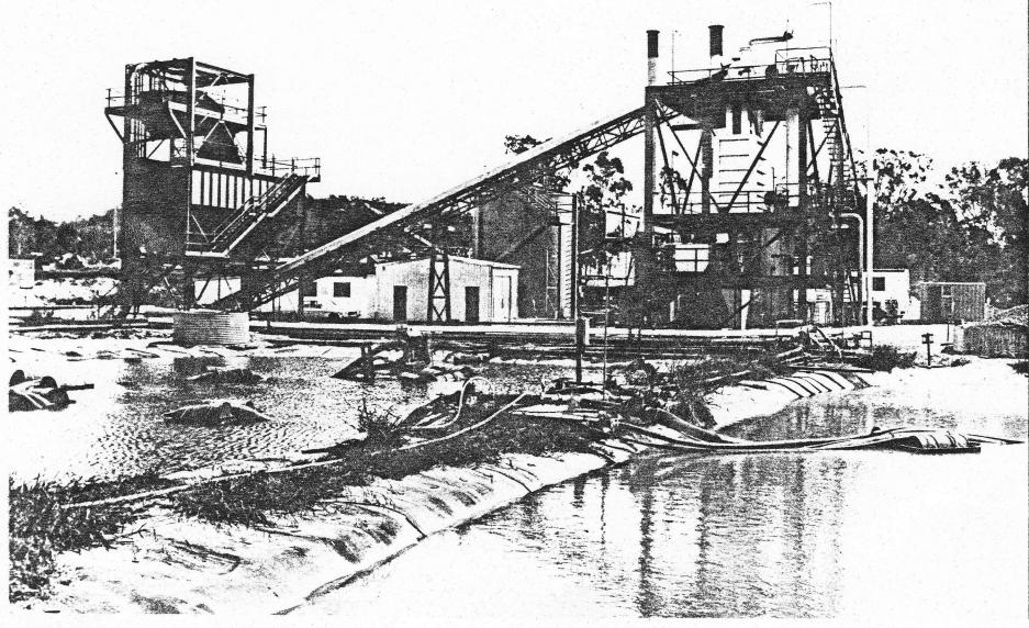
Fig. 1. Overall View of the Pilot Plant Facility.
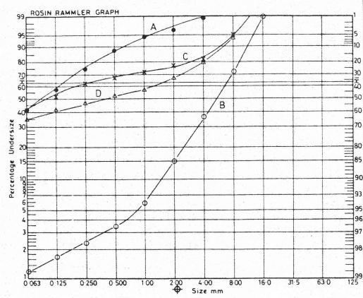
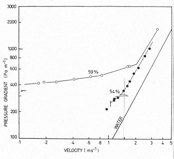
Fig. 2. Coal size distributions
Fig. 3. Behaviour of Coal A in the 100mm pipe.
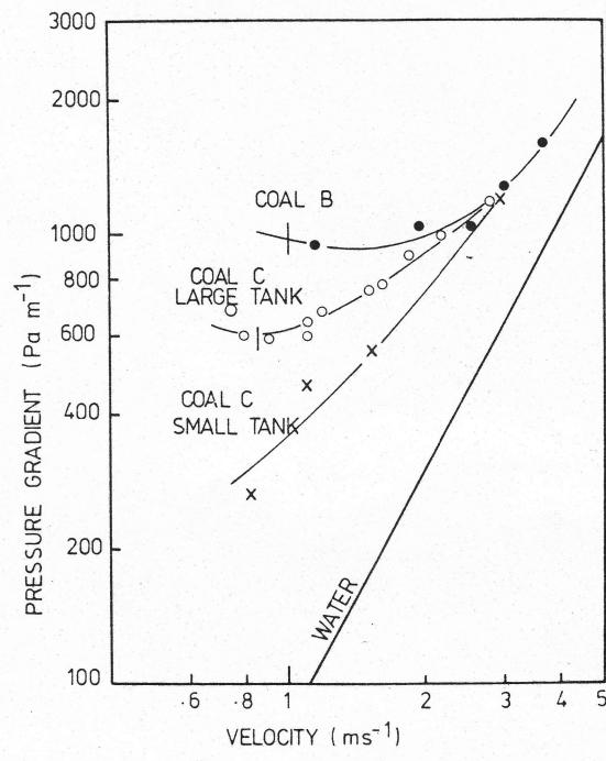
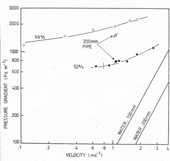
Fig. 4. Behaviour of the coarse coal slurries in the 100 mm pipe.
Fig. 5. Behaviour of stabilised slurry D in 100 mm and 200 mm pipe.
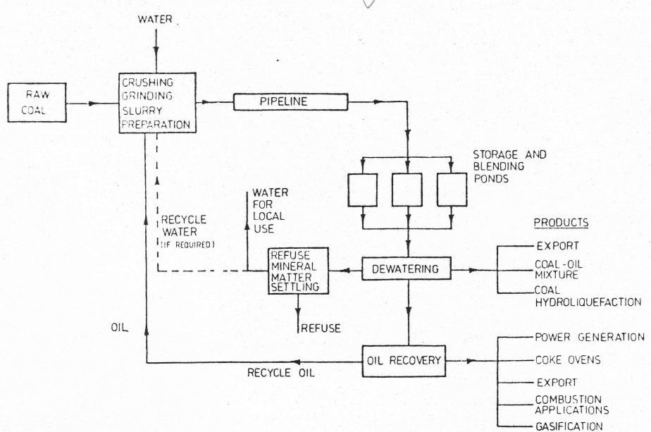
Fig. 6. Schematic diagram of the IPTACCS process
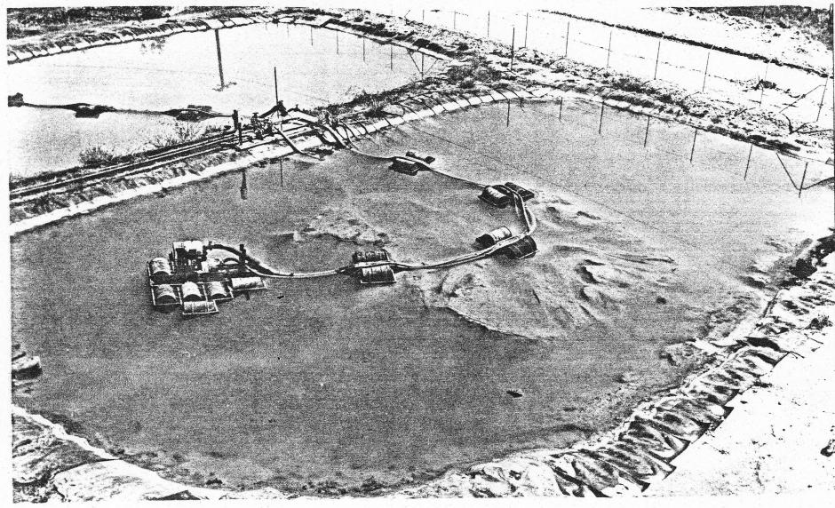
Fig. 7. Product storage ponds containing agglomerated coal and refuse mineral matter
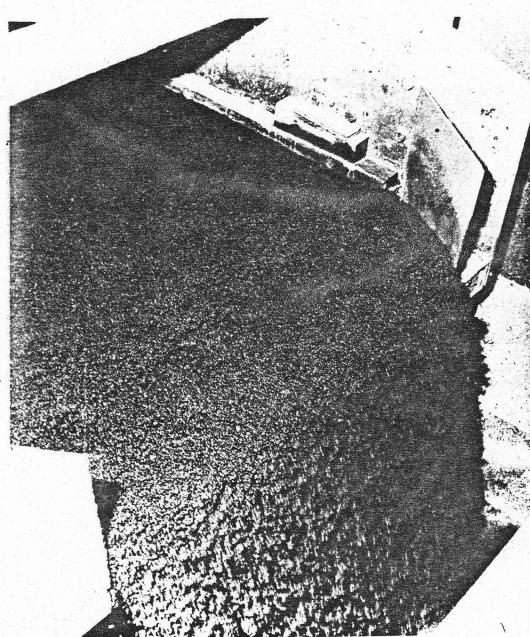
Fig. 8(a) Product being dewatered from the pipeline slurry over the screen.
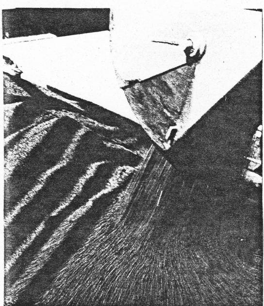
Fig. 8(b) Dewatered product being discharged from the product hopper to a truck for transport to the Newcastle Steelworks for coking trials.
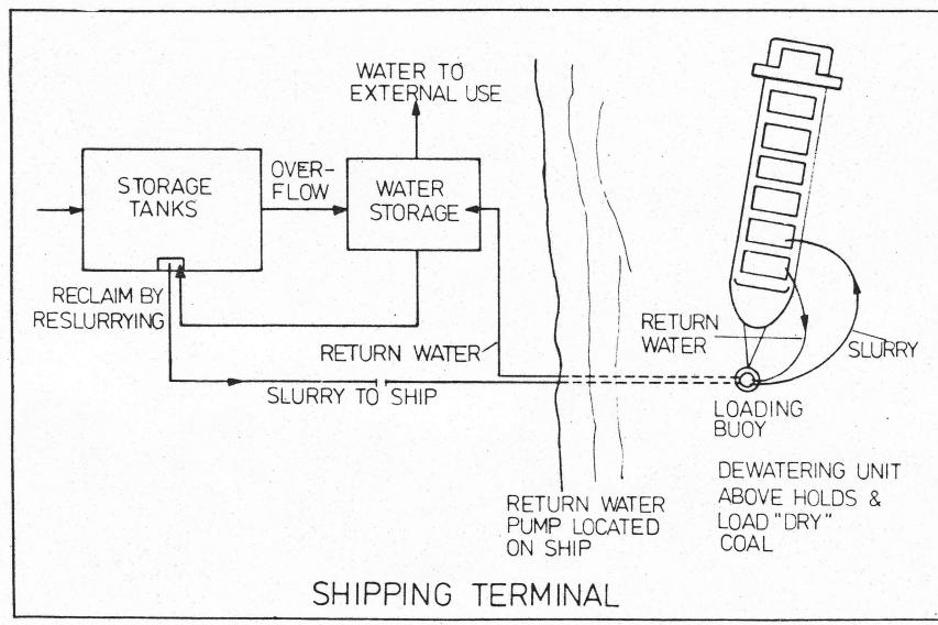
Fig. 9. Slurry Storage and offshore loading terminal.
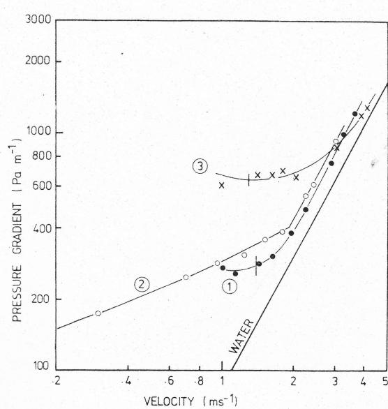
Fig. 10. Behaviour of agglomerated slurries.