This HTML edition contains selectable text extracted from the original PDF. Layout-aware OCR was used to recover reading order, figures and equations; minor recognition errors may remain. Consult the PDF for the authoritative layout, figures and equations.
Sand Bypassing Using the Shore Parallel Trap
D. FOSTER
Unisearch Ltd, Tasmania
A. THOMAS
Slurry Systems Pty Ltd, NSW
R. BRINDLEY
Department of Marine & Harbours, WA
K. BLAKE
Clough Engineering Group, WA
1. INTRODUCTION
Littoral drift of sand along coastlines can result in sandbars across river mouths and harbour entrances. These sand bars may cause navigational problems. There are a number of methods of removing sandbars including periodic dredging conventional dredges. In instances where the dredging wave climate attracts cost effectively on one of the more prevailing wave climate methods is a fixed sand bypass system consisting of fixed jet pumps buried in a sand trap located updrift of the entrance. The littoral drift sand is intercepted by the trap. The littoral drift by the jet pumps and transported via a submarine pipeline across the entrance for discharge on the downdrift beach. The sand then resumes its longshore movement.
2. LITTORAL DRIFT
2.1 Suspension of Sand
A wave moving towards a beach breaks when it reaches a water depth equal to about 1.3 times the wave height (1). Breaking results in a dissipation of wave energy by the generation of turbulence in the water and by the transport of sediment lifted off the bottom by the turbulent water. The maximum water velocity under a breaking wave is approximated by solitary wave theory to be
where is gravitational acceleration, is the height of the wave and is the depth of water. Substituting at the breaking point equation 1 becomes
The table below shows the maximum velocity calculated using equation 2 for various wave heights.
| Wave Height (m) | 0.5 | 1 | 2 | 3 | 4 | 5 |
| Velocity (m/s) | 3.4 | 4.7 | 6.7 | 8.2 | 9.5 | 10.6 |
Even for waves of moderate height the predicted velocities are substantial and more than sufficient to suspend sand.
The above predictions derive from solitary wave theory. Of the four types of breakers (spilling, plunging, collapsing and surging) spilling breakers most closely resemble solitary waves.
Spilling breakers differ little in fluid motion from unbroken waves and generate less bottom turbulence and so tend to be less effective in transporting sediment than plunging or collapsing breakers. The most intense local fluid motions are produced by plunging breakers. As the wave moves into shallower depths the front face begins to steepen. When the wave reaches a mean depth equal to about its height it breaks by curling over at the crest. The crest of the wave acts as a free falling jet that scours a trough in the bottom.
To a lesser degree unbroken waves can also suspend sand with their suspending capability reducing with Roy,(2) wave depth. Studies (e.g. Gordan and Hoy,(2)) have shown that appreciable sand movement can occur out to depths of 20 metres. However littoral drift of sand suspended by unbroken waves is of little significance as regards formation of sand bars across entrances.
2.2 Natural Bypassing
Littoral drift of sand along a coastline is predominantly due to waves striking the coast at an angle other than normal. This causes the sand, suspended by wave action mainly in the surf zone, to be transported along the beach. When this littoral drift sand intercepts an entrance much of it is deposited across the entrance. This is because the waves entering the deep water of the entrance no longer break and so lose most of their suspending capability. Non breaking waves beyond the surf zone will still continue suspending the same amount of sand so this sand will not be deposited but will continue past the entrance. Sand continues to deposit across the entrance until a sand bar is formed. This then causes the waves to break allowing them to suspend sand again and the littoral drift process continues past the entrance. This is the natural process by which littoral drift sand is bypassed across an entrance. If this process with its resulting means of bypassing the sand must be employed.
3. SHORE NORMAL TRAP
Probably the most successful fixed sand bypass system is the Nerang River entrance system on the Gold Coast, Queensland. The sand trap in this system is normal to the shore. A jetty spans the 300 metre length of the trap with jet pumps located on the jetty pylons at 30 metre spacing.
Sand accumulated in the trap is lifted by the jet pumps into a sloping flume running the length of the jetty. The sand flows by gravity down the flume into a sump on the shore. This sump feeds
into a centrifugal pump which pumps the sand through a pipeline laid beneath the entrance to the downdrift side of the entrance. The sand is deposited on the beach, picked up by wave action and resumes its littoral drift along the shore. By this means the formation of a sand bar is avoided.
The shore normal trap at Nerang was designed to intercept littoral drift over the whole of the active surf zone. When the trap is empty it is refilled principally from the sides by littoral drift.
4. SHORE PARALLEL TRAP
4.1 General
Although the littoral drift component of sand movement is of ultimate concern there is a much greater oscillating movement of sand in the surf zone towards and away from the shore. This oscillating movement occurs as the waves advance to and recede from the beach. Just as the normal component of wave velocity is generally far greater than the shore parallel component, so the rate of oscillating sand movement normal to the beach is far greater than the littoral drift component. This suggests the possibility of a trap orientated parallel to the shore. There are two means whereby sand enters such a trap; direct feed and reverse littoral drift feed.
4.2 Direct Trap Feeding
Consider a trap orientated parallel to the shore and situated close to the shoreline. As littoral drift sand moves along the coast it follows a "zig zag" course moving in and out from the shore as the waves advance and recede. Under this action some of the moving sand will be fed directly into the trap. The proportion entering the trap directly in this manner will depend on the length of the trap, the rate of littoral drift and the width of the surf zone. It should be noted that each particular grain of sand does not necessarily traverse the full "zig zag" path. Some sand may stay predominantly in the near shore zone for example. However any removal of sand from the system into the trap results in a local decrease in concentration. This lost sand is then compensated for either by migration of suspended sand into the depleted area from nearby areas or by additional suspension of sand from the bottom nearby.
4.3 Reverse littoral Drift Feed
Depending on the trap size and other conditions some of the littoral drift sand may not be trapped and will continue past the trap and accumulate against the breakwater as shown in Figure 1. The fillet of sand so formed eventually becomes sufficiently large such that the angle of incidence of the waves striking the fillet are reversed. This causes a reverse littoral drift towards the trap.
4.4 Location of Trap
The fillet storage volume and reverse littoral drift process means the capacity of the sand pumping system does not have to match the peak storage littoral drift rates. The system can be designed for a lesser transfer rate.
The positioning of the trap in relation to the breakwater dictates the storage volume available
in the fillet. The further the trap is away from the breakwater the greater the potential storage volume. However the greater the distance between the trap and the breakwater the further the fillet will need to extend offshore to present the required reverse angle of incidence to the waves and generate the necessary reverse littoral drift. There is then the possibility of sand migrating around the tip of the breakwater into the entrance.
Another consideration is that some of the sand needed to form the fillet is permanently lost from the coastal process. This loss will deplete downdrift beaches to a certain extent. The positioning of the trap is therefore a compromise between peak storage volume and avoidance of too greater permanent sand loss. In practice a trap located about 100 to 200 metres from the breakwater is ideal.
4.5 Trap Utilisation
Sand movement is greatest in the near shore zone. This has been illustrated by experience at Nerang where the near shore jet pumps are required to pump the majority of the sand with the outer jet pumps operated less frequently. The parallel trap is located in the near shore zone where activity is greatest. The size of the trap can therefore be reduced.
Any sand which passes the trap accumulates against the breakwater and is returned to the trap by the reverse littoral drift process.
5.0 MODEL STUDIES FOR DAWESVILLE PROJECT
5.1 Dawesville Project
The Department of Marine and Harbours (DMH), Western Australia is considering construction of an artificial channel between the sea and Peel Inlet near Mandurah to improve flushing of the estuary (see Figure 1). There is an estimated nett northerly littoral drift of 80,000 cubic metres per year along this coastline. To avoid formation of a sand bar across the entrance to this proposed channel it is intended to construct a fixed sand bypass system. Originally a system similar to the successful Nerang installation was proposed and Clough Engineering, Slurry Systems and Unisearch were commissioned to perform a feasibility study into such a system. During this study discussions between all four participating organisations resulted in the idea of the parallel trap.
5.2 Hydraulic Model
To demonstrate the effectiveness of the parallel trap basin model studies were conducted. The model was constructed at the Coastal and Hydraulic Engineering Laboratory at Floreat Park, WA with the assistance of the DMH. The operation of the model was carried out by DMH staff under the direction of Unisearch Ltd.
The model was a 1:100 scale representation of the Dawesville beach and the proposed southern breakwater. The model basin was rectangular in plan with a 1 in 2 slope energy absorption beach around its perimeter formed with 12 mm crushed blue metal.
The irregular sea state of the prototype was simplified and generated as uniform regular waves by an 11 metre wide wave paddle driven by a
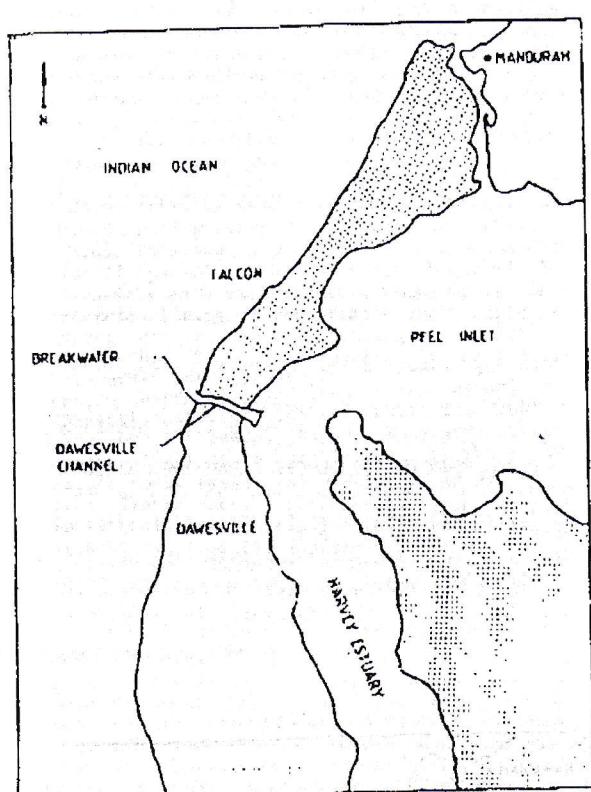
FIGURE 1. DAWESVILLE CHANNEL LOCALITY PLAN
variable speed electric motor. Waves were generated in a mean water depth of 340 mm. The waves then propagated over a uniform transition alope onto the reproduced bathymetry of the area under investigation. Wave guides were installed to prevent premature decay in the wave shape from side diffraction effects. Other preventative measures to limit scale effects included a wire mesh wave filter in front of the paddle to reduce wave reflection from the paddle, and the use of fins attached perpendicular to the face of the paddle to suppress the development of edge waves along its length.
The bed material used in the model was fine sand having a median grain size of 0.4 mm. The trap was modelled with a perspex box for prototype lengths of 50 and 100 metres. Sand was removed from the trap manually.
The model is shown in Figure 2.
5.3 Model Operation
To simulate a northerly littoral drift wave conditions were introduced into the model with the following model characteristics:
- - Wave height 20 mm
- - Wave period 2 secs
- - Angle attack on updrift beach 10 degrees. This represents the typical south west swell direction in summer at Dawesville.
As the breakwater acts as a total littoral drift barrier the longshore transport rate in the model can be determined by measuring the volume change with time of the sea bed at the breakwater. The longshore transport to the north so obtained was
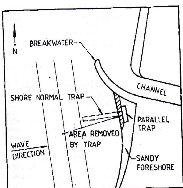
FIGURE 2. DAWESVILLE CHANNEL SAND BYPASS MODEL
0.6 cubic metres per hour.
In operating the model the rate of filling of the trap was observed for various trap orientations and for incident waves with measured parameters. The 100 metre (prototype) trap was tested in both the shore normal and shore parallel orientations.
5.4 Model Scaling
The horizontal scale was selected to be 1:100. The approximate vertical scale was selected on the following basis. In the model onshore/offshore movement of sand was observed to be limited to a water depth of 30 mm. Measurements of prototype beach profiles undertaken by DMH on sandy beaches along this section of the coast indicate that significant sand movement takes place shoreward of the 4 metre depth contour. This results in a vertical scale of 1 in 133 and this was adopted for this study. The volume scale is therefore 1.33 x 10 6 .
The geomorphological time scale for operation of the model was estimated as follows. The model time required to reproduce an average annual littoral drift of 80,000 cubic metres can be calculated from:
Model Rate(cu.m/h) x Volume scale x Model Time (h)
= 80,000 cu.m/y Prototype
The model time so calculated to reproduce 1 year prototype is 1 hour.
Slug flows of sand movement in the model were reproduced by varying the interval between sand accumulation and sand bypassing. For example the design criteria requires the plant to be able to handle a slug of 30,000 cu.m in a 7 day period. If there is no sand bypassing during such an event prototype beach changes would be represented in 0.4 hours in the model.
5.5 Results
A number of tests were conducted. In one test the equivalent of several years sand supply was allowed to accumulate against the breakwater burying the trap. Sand was then removed from the trap intermittently as it filled or near filled. The accumulated sand against the breakwater was rapidly transported to the trap and removed.
Overall conclusions reached were:
(a) The trap action was capable of supplying sand to the wave at rate greatly in excess of the average annual littoral drift rate of 80,000 cubic metres per year.
(b) Sand slugs resulting from storms could be allowed to accumulate against the breakwater for subsequent removal.
(c) Under normal operation there was little or no chance of the trap being "sanded out" (access lost to the ocean). Sand slugs resulted in the system could be cleared by artificially opening a small cut to connect the trap to the ocean.
(d) Both the 50 and 100 metre equivalent trap lengths performed satisfactorily with only a small lowering of efficiency as the length is reduced.
(e) The prototype trap length could be reduced, although the minimum length possible required further testing.
(f) The tests clearly indicated that the shore parallel trap system was hydraulically more efficient for wave transport of sand to the trap than a shore normal system.
6.0 ECONOMIC ADVANTAGES
The major economic advantage of the parallel trap is that offshore structures are minimised. The shore normal trap configuration at Nerang involves a 500 metre long jetty on an exposed coastline subject to regular cyclones. There is considerable cost in such a structure.
With a parallel trap the whole of the trap is closer to the shore. It is possible to use land based methods of construction for the jetty if the fillet of sand which forms behind the breakwater is allowed to advance seaward prior to construction. This obviates the need for an expensive marine construction plant. Once the bypass system has been completed it can be operated to draw the beach back to the desired alignment.
In situations where the trap must be excavated in rock, such as at Dawesville, the parallel trap has advantages since it is cheaper to excavate in shallow water close to the shore. Once again land based excavation and construction methods may be utilised.
7.0 APPLICATION TO DAWESVILLE
The proposed Dawesville sand bypass system will use a 50 metre long parallel trap situated approximately 35 metres offshore. The trap will be excavated in rock to a depth of 7 metres.
8.0 CONCLUSIONS
Sand bypassing using a fixed jet pump installation has been considered with attention given to both the shore parallel and shore normal sand trap configurations. The shore parallel trap is shown to have advantages over the trap orientated normal to the shore. Model tests conducted for the proposed sand bypass system at Dawesville, Western Australia confirmed the suitability of the shore parallel trap.
8.0 REFERENCES
1. Munk, W.H. "The Solitary Wave Theory and its Application to Surf Problems", Annals of the New York Accademy of Sciences, Vol. 51, 1949, pp 376-462.
2. Gordon, A.D. and Roy, P.S. "Sand Movements in Newcastle Bight", Proc. 3rd Australasian Conf. on Coastal and Ocean Engineering, Melbourne, 1977, pp 64-69.