This HTML edition contains selectable text extracted from the original PDF. Layout-aware OCR was used to recover reading order, figures and equations; minor recognition errors may remain. Consult the PDF for the authoritative layout, figures and equations.
Technical Considerations for
Pipeline Transport of Lump Coal
A.D. THOMAS, PhD Manager,
N.T. COWPER, BE Managing Director,
Slurry Systems Pty Ltd, Sydney,
SUMMARY
Australia, being the largest exporter of coal in the world, has considerable interest in the efficient transport of export size coal. This has prompted a number of research projects over the past fifteen years and Australia has lead the world in research into the pumping of lump coal. The aim of these projects was to achieve reliable transport of coal in buried pipelines with low pressure gradients and low pipe wear.
Technologies for pipeline transport of coal are considered. A new system using a high density Special Vehicle Slurry is summarised and shown to be economically competitive with either road or rail alternatives.
1. INTRODUCTION
Although Australia is the largest exporter of coal in the world it is facing increasing competition from countries such as South Africa and Indonesia. The recent political changes in the Soviet Union may also mean Japan obtaining increasing amounts of coal from that country. In Australia, transport charges from the mine to the port are typically one quarter from the third of overall production costs. Any reduction in transport costs has a significant impact on the export coal price.
Environmental considerations are also becoming increasingly important. A buried pipeline offers the most environmentally attractive solution to overland coal transport.
Long distance transport of coal has been a reality for over twenty years since the Black Mesa pipeline began operation in 1970 in the U.S.A. The Black Mesa pipeline transports 5 Mtpy of coal over a distance of 450 kms but is limited to fine coal with a top size of only 1 mm. Coal exported from Australia is typically 50 mm top size and to be commercially successful in Australia a pipeline system must transport lump coal.
Australia is at the forefront of research into methods of pumping lump coal and a number of alternative technologies have been investigated. The present paper considers the various technologies for transport of coarse coal with particular emphasis on the flow mechanisms involved. The paper summarises the benefits of a new technology using a special vehicle slurry as a transport media slurry.
2. REQUIREMENTS
There are two major requirements of a successful lump coal pipeline system. The operating velocity should be in the range 1 to 2 m/s and pumping pressures must be low to moderate 2 m/s and third requirements are met. This is automatically satisfied if the first two requirements are met.
There are thousands of kilometres of water and oil pipelines throughout the world and they all have one thing in common: The flow velocity is in the range 1 to 2 m/s. This velocity range results in minimum cost (pump station and pipeline) (which decreases with increasing velocity due to the smaller pipe diameter required) and operating costs (which increase with increasing velocity due to higher pressure gradient). To be competitive a coal pipeline should also operate in this same velocity range. Hence the Black Mesa pipeline operates at 1.5 m/s.
resulting pressure gradient should be not too different from the pressure gradient when pumping water or oil at the same velocity. Ideally the pressure gradient should not exceed 2 to 3 times that of water headloss.
Internal pipe wear is a major consideration in slurry pipelines. In steel pipelines the oxide layer which develops when corrosion serves to protect the pipe by inhibiting the corrosion process. When the pipeline transports abrasive slurry, the oxide layer may be continuously removed by the slurry flow which accelerates the corrosive process.
Providing the particle settling predilection is low, erosive pipe wear can be kept within acceptable limits. This, together with corrosion control measures, allows use of ordinary steel pipe. If wear resistant linings must be used the capital cost can be doubled.
3. TRANSPORT MECHANISMS
There are two mechanisms available for transporting solids in pipes.
3.1 Turbulent Suspension
If the particle settling tendency is sufficiently small the particles are maintained in suspension by the turbulent eddies. The solid particles follow the fluid motion. This form of transport results in low pressure gradient and minimum pipe wear, especially if the velocity is low. A necessary requirement is turbulent flow.
The slurry flow can be analysed as if it is a homogeneous fluid having a density and viscosity plot of pressure gradient versus velocity approximates a straight line of slope approaching 1.7-2, paralleling the water curve.
At low velocities pipe steel wear is minimal but if the velocity is high some pipe wear can occur. This tends to be distributed around the circumference and not in the pipe invert as with heterogeneous slurries.
3.2 Sliding Bed Transport
Particles too large to be suspended by turbulence are dragged along by the drag force exerted by fluid flowing around them. The particles congregate near the bottom of the pipe and move as a saltating or sliding bed.
The flow can be analysed as a sliding bed (1). The bed of solids is driven along by the axial force due to the pressure difference across the ends and by the shear force exerted by the fluid flowing across the
top of the bed. Movement of the bed is resisted by solid/solid friction between the bed of solids and the pipe wall. The force balance between the driving and resisting forces determines the flow. Wilson found that a similar analysis applies even when the solids are saltating (bouncing) along the bottom rather than sliding.
The driving force required, and hence pressure gradient required, depends on the sliding friction coefficient and the effective mass of the solids after allowing for buoyancy. Because solid/solid friction is essentially independent of velocity the pressure gradient/velocity plot tends to be near horizontal, except for particles that transition size between suspended and sliding bed transport, in which case the pressure gradient/velocity plot has a pronounced negative slope.
For lump coal transported as a sliding bed in water the pressure gradients are high as is the pipe wear rate. Pipe wear is concentrated in the bottom zone of the pipe.
The above discussion concerns sliding bed transport where the fluid flow is turbulent. Lump coal is also transported by sliding bed mechanism under laminar flow conditions (2). This occurs if the there is a high proportion of fine coal forming a viscous vehicle slurry.
4. FACTORS AFFECTING TRANSPORT MECHANISM
4.1 Coal in Water
For coal particles in water the changeover from suspension type flow to saltating-sliding bed type flow occurs at quite small particle size. Figure 1 shows predicted behaviour of mono-sized coal particles at 50% concentration in a 300 mm diameter pipe. Coal SG is assumed equal to 1.40. The vertical bars indicate the deposit velocity; the velocity below which a stationary bed of solids forms in the bottom of the pipe. It is desirable to operate slightly above this velocity, typically 0.3 m/s above.
Using the theory of Wilson (1) as modified by Thomas (3), it is possible to calculate the proportion of particles transported as bed load (saltating or sludding). The remainder of the particles are suspended by turbulence. At 1.5 m/s the predicted percentage of particles travelling as bed load is 0.000006% for 0.1 mm particles, 0.44% for 0.2 mm, 5.5% for 0.3 mm, and 14% for 0.4 mm. i.e. as the particle size increases from 0.1 mm to 0.3 mm the proportion travelling as bed load changes from being insignificant to significant.
The increase in bed load between 0.1 mm and 0.3 mm results in a marked change in behaviour as seen in Figure 1. The flow behaviour changes from one paralleling water behaviour for 0.1 mm particle size to one experiencing obvious sliding bed influence at 0.3 mm. Allowing for an operating velocity margin above deposition the preferred operating velocity range of between 1 and 2 m/s is only possible up to about 0.3 mm particle size. The optimum pressure gradient limit of about double that of water places a similar upper limit on particle size.
Figure 1 applies to mono-sized particles but also approximates the behaviour of a wide particle size distribution by substituting the median size ( ). For crushed coal the top size ( ) is typically about 5 times the median size, indicating the change in behaviour occurs between top sizes of 0.5 mm and 1.5 mm. The 1 mm top size of the Black Mesa coal falls in this range.
FIG. 1 COAL IN WATER
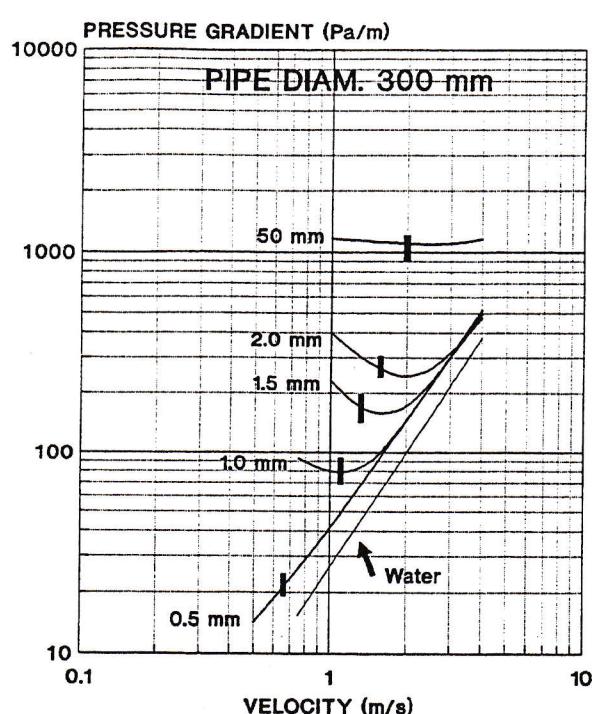
Export size coal of 50 mm top size (10 mm median size) exhibits the characteristic flat pressure gradient curve indicative of sliding bed, or fixed bed flow, with the attendant likelihood of pipeline plugs. In the target velocity range of 1 to 2 m/s the pressure gradient is and order of magnitude higher than for 0.1 mm coal. Pipe wear is correspondingly very high, typically about 20 mm/y for steel pipe. Even wear resistant lined pipe lasts only a few years.
4.2 Effect of Increased Viscosity
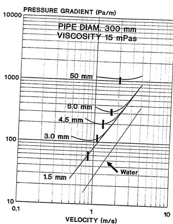
Figure 1 applies to coal in water. The fine particle portion of a slurry results in an increase in viscosity. Typically a slurry viscosity of around 15 mPas is about the highest which can be achieved before flow tends from turbulent to laminar flow. This is a 15 fold increase above the viscosity of water. Figure 2 shows predicted behaviour at this viscosity. Comparison with Figure 1 indicates the increased viscosity has resulted in the particle limit for economic transport is increased by a factor of 3 to a topsize of 4.5 mm. Whilst this is an improvement it is still well below the desired 50 mm top size.
Comparison between Figures 1 and 2 indicates little benefit results from the higher viscosity when pumping 50 mm top size coal.
4.3 Effect of Increased Slurry Density
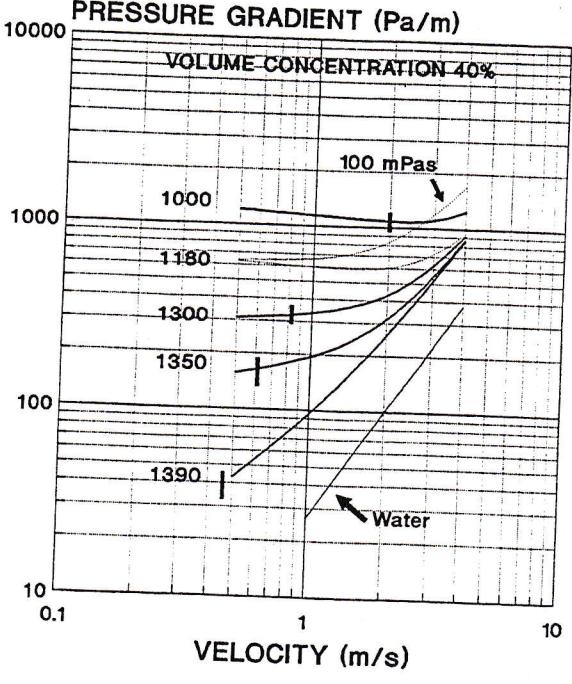
The alternative for reducing the settling tendency of the lump coal is to employ a high density, fine particle vehicle slurry. Figure 3 shows predicted behaviour in a 300 mm diameter pipe of 50 mm top size coal at a volume concentration of 42% in theoretical vehicle slurries of various densities. For the analysis the viscosity of the vehicle slurry is assumed constant at 15 mPas for all except the single 100 mPas case indicated.
A progressive increase in vehicle density from 1000 kg/m 3 (water) to 1390 kg/m 3 results in near homogeneous type flow, as evidenced by the close
FIG. 2 EFFECT OF HIGHER VISCOSITY
paralleling of the water curve. The deposit velocity is reduced to less than 0.5 m/s. At a suitable operating velocity of 1.8 m/s the pressure gradient is 210 Pa/m, some 2.5 times that of water alone. The twin goals of operation between 1 and 2 m/s at a pressure gradient between 2 and 3 times water are achieved.
If the vehicle slurry density is made exactly equal to the density of the lump coal there is no settling tendency and the coarse coal/vehicle slurry will operate in homogeneous flow.
FIG. 3 EFFECT OF SLURRY DENSITY
50 mm TOP SIZE, D = 300 mm
5. REVIEW OF PIPELINE TRANSPORT METHODS
5.1 Lump Coal in Water (Brute Force Pumping)
It is technically feasible to pump lump coal at relatively low concentrations in water. It is common within coal washeries and has been used to transport coal over a few kilometres (4). However, as is illustrated in Figure 1, it requires high velocities and high pressure gradients.
The high velocity and sliding bed flow mechanism causes very high pipe steel wear rates. The pipe is required to be layed on top of the ground to permit periodic turning to increase pipe life (the major wear occurs at the bottom). Even then steel pipe typically only lasts a few years.
The high pressure gradients mean a centrifugal pump is required about every 500 to 700 m pumping distance. Even a high pressure positive displacement lock hopper type pump of say 10 MPa discharge pressure will only pump about 10 kms.
5.2 Stabilised Slurry Transport
The concept of transporting lump coal in a fine coal vehicle slurry under laminar flow conditions was first reported by Elliot and Glidden (5). Pertuit et al (6) gave the concept the name Stabflo and carried out further tests. In Australia subsequent investigations were conducted by Thomas (2). The CSIRO instigated a major loop testing program to develop stabilised slurry transport in 1978.
The stabilised flow concept involves pumping the lump coal with fine coal at relatively high concentration with water. At suitable concentrations and ratios of fine coal to lump coal, the Bingham plastic properties of the vehicle slurry result in a homogeneous like mixture. In particular, in static conditions, the lump coal is locked in suspension without settling by the yield stress of the vehicle slurry. This is a desirable property.
However, Thomas (2) showed that once the mixture is sheared in pipeline flow the yield stress no longer supports the lumps and they drop to the bottom of the pipe and are transported by a sliding bed mechanism. This means the pressure gradients are similar to lump coal in water although reduced somewhat because of the buoyancy effect of the higher density and viscosity of the vehicle.
Typically the total solids concentration is around 70% with fine coal making up approximately 40% of the solids. The resulting vehicle density is around 1180 kg/cu.m. The dashed curves shown in Figure 3 are predictions for this vehicle density and viscosities of 15 and 100 mPas. The latter value is typical of the plastic viscosities reported by Duckworth et al (7). The pressure gradient is reduced to about half that for the same coal in water. However it is still about an order of magnitude higher than water alone. Furthermore the flat shape of the curves indicates significant sliding bed component suggesting a pipe wear problem.
Until recently the researchers of the stabilised coarse coal technology were convinced that scale up from loop test data to larger diameter commercial pipelines was based on a Bingham plastic model and that pipe wear was not a problem since the fine slurry vehicle created a fluid boundary layer that eliminated pipe wear.
diameter. The larger the pipe diameter the lower the pressure drop and hence, the perceived commercial attraction of the stabilised concept. The energy required per tonne of coal transport was quoted as less than the Black Mesa Pipeline. The basic premise of maintaining coarse coal particles in suspension by fine slurry yield stress has proven not valid.
Although the predictions of Figure 3 are for turbulent flow experience has shown that the head loss is similar to stabilised commercial flow headlosses. This is to be expected since few of the particles are supported by turbulence so the sliding bed component is similar in laminar flow where there is no turbulent support. The predicted pressure gradient in the velocity range 1 to 2 m/s for a vehicle density of 1180 kg/cu.m and viscosity of 100 mPas is similar to the measured pressure gradients of Duckworth et al (7) for stabilised flow operation in this size pipe.
One advantage of the Stabflo concept is pipeline operability, the pipeline can be shutdown with slurry in the line and readily restarted without plugging.
In summary, although stabilised laminar flow can result in reduced pressure gradients they are still too high for economic long distance operation. The operating velocity can be low but the lump coal is transported by a sliding bed mechanism indicating a potential pipe wear problem. A major disadvantage is the high proportion of very fine coal (40%) required.
5.3 High Concentration Coarse Coal in Water
Recently the pumping of lump coal with minimum fines, i.e. typical export coal, has been extensively tested in Australia (8). The granular mixture is packed into the pipe at concentrations approaching the maximum packing density (70 to 75% by weight). The solids are packed so tightly that a separate stationary bed of solids cannot form and the whole mixture can be pumped at very low velocities, less than 1 m/s. The researchers in this technology also considered flow on a Bingham Plastic model.
Because of the low velocity and tight packing of particles there is negligible turbulent support of particles and the flow mechanism is sliding bed type. The pressure gradients are consequently very high, in excess of 1000 Pa/m (c.f. Figure 3). Because of the capability of operating at low velocity, pipe wear is not as severe as for conventional turbulent flow of lump coal. Nevertheless it is still too high to permit use of buried unlined steel pipe.
An additional negative on this technology is operability. Any interface between the high concentration coarse coal and water batches breaks up the coarse coal leading to pipeline plugs during shutdown and restart. Because of these three problems; high pressure gradient, unacceptable pipe wear rates and inappropriate pipe wear effectively been abandoned.
6. SVS TRANSPORT
6.1 Basic Concept
In Section 4 it was shown how for coal particles in water the demarcation between the desired fully suspended flow and sliding bed behaviour occurs at coal top sizes around 1 mm. The goal is to somehow increase this demarcation to around 50 mm to allow economic transport of lump coal homogeneously in turbulent flow. It was shown how increasing the viscosity of the suspending medium cannot achieve the desired low pressure gradient and minimal pipe wear rate. The alternative was to increase the vehicle
density to near that of the lump coal, i.e. achieve near neutral buoyancy.
All previous technologies have failed because they have not used high density vehicles. They have either relied on high viscosity (stabilised slurry) or have ignored the penalties of sliding bed operation (lump coal in water at both high and low concentrations).
The SVS (Special Vehicle Slurry) system (Patent. Pending) utilises a special high density slurry to achieve the desired vehicle density of around 1400 kg/cu.m.
The SVS slurry is specifically formulated to create properties suited for long distance pipelining. The properties include, slurry specific gravity in range of 1.35 to 1.45 for neutral buoyancy, low rheology, shutdown/restart operability characteristics, and non contamination of lump coal. The SVS slurry is magnetite based.
Magnetite is a high density (SG 4.9) material commonly used in coal washeries. Magnetic techniques can be used to separate it from the slurry for recycling purposes. However even ultrafine magnetite (95 to 98% minus 53 microns) exhibits some settling tendency in pipeline flow at moderate velocities, i.e. the magnetite migrates towards the bottom of the pipe. This means the required near neutral buoyancy is not achieved over the whole pipe cross section.
6.2 Flow Behaviour
The near neutral buoyancy of the lump coal in the vehicle slurry creates a mixture which flows in a similar manner as fine coal in water. Figure 4 shows data obtained as a 105 mm diameter pipe. The first data set is for fine coal of top size 0.5 mm at 44% concentration. Also shown is data set for lump coal (top size 50 mm) in SVS medium at volume concentrations of 14% and 22%. Above 1.5 m/s the lump coal exhibits similar pressure gradient as the fine coal confirming the similar flow behaviour. This means the 20 years experience with the Black Mesa fine coal pipeline is applicable to the SVS lump coal transport system.
FIG. 4 LUMP COAL IN SVS
105 mm PIPE
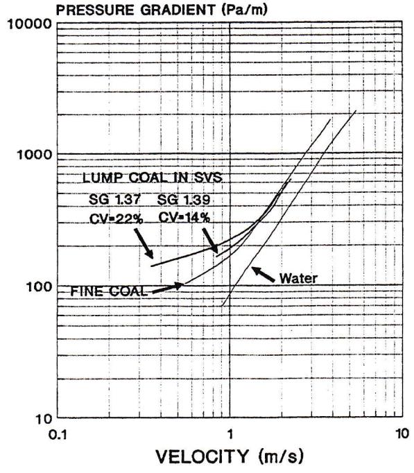
Figure 4 illustrates the pressure gradient for lump coal in SVS is less than twice that of water alone.
6.3 System Description
The SVS transport system consists of two pipelines, a main pipeline transporting the lump coal and a return pipeline for returning the special vehicle slurry. Both pipelines are unlined steel pipe, fully welded and buried.
At the preparation facility the lump coal is fed by conveyor into an agitated tank containing vehicle slurry. From this tank the mixture is fed to a positive displacement type pump and then to the pipeline. The pumps are modified commercially available concrete or piston type pumps with slide gate valves, suitably upgraded for continuous service, or else custom built lock hopper type pumps. For distances less than about 70 kms only one pump station is required. Greater distances will require a booster pump station every 70 kms.
At the pipeline terminal the slurry enters the separation facility. The plus 0.5 mm material is separated over a series of sprayed screens then dewatered in basket centrifuges and conveyed to stockpile. The minus 0.5 mm material comprises the vehicle slurry plus any fine coal product resulting from attrition of the lump coal during transport. The minus 0.5 mm stream is split in a ratio depending on the proportion of attrition products. A bleed stream encovers fine attrited coal from the special vehicle slurry. The majority of minus 0.5 mm coal is transported as a fines slurry in batch mode and goes on a fine coal slurry storage tank. The bleed stream ortion is sent to magnetic separators where the agnetite is removed and sent to the vehicle storage tank. The separated fine coal attrition and fine coal products are thickened then dewatered using a combination of screen bowl centrifuges and belt press ilters. The dewatered fine coal then joins the dewatered plus 0.5 mm coal on the stockpile. From the vehicle storage tank the vehicle slurry is pumped in the return pipeline back to the preparation facility or recycling. All equipment used is standard coal cashery equipment.
major advantage of the SVS system is that since it ses a recycle pipeline the system uses no water ther than that required for the initial fill.
.0 TRANSPORT COSTS
- 1 2 SVS System
To illustrate typical costs involved, the transport for 3 Mtpp of coal over 50 kms is considered. The ystem involves a preparation facility to receive the coal, 400 mm diameter main and return pipelines with single pump station on each, and a separation acility at the terminal. Total power required is ,800 kW.
१९ के कार्यालय कार्य किये गये हैं:
| M$ | ||
| Preparation Facility | 3.5 | |
| Pipelines | 21.0 | |
| Pump stations | 9.0 | |
| Separation Facility | 8.5 | |
| TOTAL CAPITAL COST | $42.0 M |
tal annual direct operating cost of the SVS system, cluding power (assumed 6 cents/kWh), labour, ocess chemicals, and maintenance supplies is $4.1
M. Over half of this ($2.4 M) is power costs. The direct unit transport cost is $ 37.4
If the annual cost of capital is assumed to be 20% of initial capital cost the overall unit transport cost is $4.37/ft.
7.2 Comparison with Lumb Coal in Water
These figures also illustrate the impracticality of the alternative lump coal in water pipeline. As discussed previously, to pump lump coal in water over this distance would require five pump stations. Although no return pipeline is involved the pressure gradient is about five times higher indicating about $30 M for pump station cost. With a pipe wear rate of about 20 mm/y the pipeline, even with periodic turning will only last about two years under continuous operation. For a 20 year life the pipeline will need to be replaced 10 times which, at the above indicated cost of $10.5 M each time places an impractical burden on system economics.
The overall 2.5 times increase in power will also increase the unit operating cost by $2/t. To this must be added the significant cost involved in periodic turning of the pipeline.
7.3 Comparison with Truck and Rail Costs
Truck and rail costs will vary considerably between different countries. Here a comparison is made between these costs in Australia. Typical trucking costs to transport coal over 50 kms are $6 to $7 per tonne. This cost assumes use of existing public roads. The government is currently proposing increases in truck licence fees to more fully reflect the damage they do to the roads. This could result in about a 3 cents per tonne-km increase meaning a $1.50/t freight increase over 50 kms. Any requirement for initial road upgrading or new roads will also add to the trucking cost. Taking these factors into account the trucking cost is about twice the SVS pipeline costs. Environmentally a buried pipeline system is immensely superior.
In Australia rail freight charges on existing rail lines are generally similar to trucking rates. The true rate is probably less than for trucks but rail freight charges are used to subsidise less profitable rail operations. Coal companies are asked to contribute additional capital when coal haulage involves the building of a new rail line. The SVS slurry alternative offers unit costs approximately 50% of current Australian rail freight rates.
- ↑ Other considerations
The SVS coal transport system can compete with road and rail haulage. The direct operating cost is very low in comparison. The majority of the operating cost relates to capital charges. However similar capital costs are involved for new rail links.
A pipeline is particularly attractive when geographic and environmental factors are important. Coal transport in the South Coast area of New South Wales is a good example. Most of the coal is presently transported by trucks but because of the steep terrain and possibility of accidents, there is increasing community resistance to trucks, especially to any further expanding of their operations. Some coal is transported by rail but because of the steep terrain the rail routes are sometimes twice the distance of a more direct pipeline route. This makes a pipeline even more attractive.
Technical considerations for pipeline transport of lump coal have been examined and the various technologies available compared with the physical requirements. It is concluded that the only economic method of pumping lump coal is to use a high density vehicle slurry to provide near neutral buoyancy for the lumps.
The SVS system uses a specially formulated patented vehicle slurry. The result is an operable pipeline system with pressure gradients similar to existing proven fine coal pipelines. The system uses a separate pipeline to return the vehicle slurry. This means following the initial filling the system uses no water.
The lump coal is separated from the vehicle slurry using standard coal washery technology and the pipeline product moisture is similar to coal washery product moisture.
9. REFERENCES
- 1. Wilson, K.C. "A Unified Physically-Based Analysis of Solid-Liquid Pipeline Flow", Proc. 4th Int. Conf. on Hydraulic Transport of Solids in Pipes, Banff, Canada, 1976. BHRA, Cranfield, U.K., pp E2/22-36.
- 2. Thomas, A.D. "Pipelining of Coarse Coal as a Stabilised Slurry - Another Viewpoint", Proc. 4th Tech. Conf. on Slurry Transportation, Las Vegas, USA, 1979. pp 196-205.
- 3. Thomas, A.D. Unpublished
- 4. Alexander, D.W., and Shaw, R.L. "Coarse Coal Transport at Loveridge Mine", Journal of Pipelines , Vol. 4, 1984, pp 235-240.
- 5. Elliot, D.E., and Gliddon, B.J. "Hydraulic Transport of Coal at High Concentration", Proc. 1st Int. Conf. on Hydraulic Transport of Solids in Pipes, Cranfield, U.K., 1970. BHRA, Cranfield, U.K., pp G2/25-56.
- 6. Pertuit, P., Tennant, J.D., Lawler, H.L., and Cowper, N.T. "Application of Stabilised Flow Concepts of Pipeline Transportation of Large Particle Coal", Proc. 3rd Int Tech. Conf. on Slurry Transportation, Las Vegas, USA, 1978. pp 164-176.
- 7. Duckworth, R.A., Pullum, L., Addie, G.R., and Lockyear, C.F. "The Pipeline Transport of Coarse Materials in a Non-Newtonian Carrier Fluid", Proc. 10th Int. Conf. on Hydraulic Transport of Solids in Pipes, Innsbruck, Austria, 1986. pp 69-88.
- 8. Bhattacharya, A., and Imrie, I. "Development of the ASEA Mineral Slurry Transport System for Coarse Coal", Proc. 10th Int. Conf. on Hydraulic Transport of Solids in Pipes, Innsbruck, Austria, 1986. pp 63-68.